The user’s needs are a priority
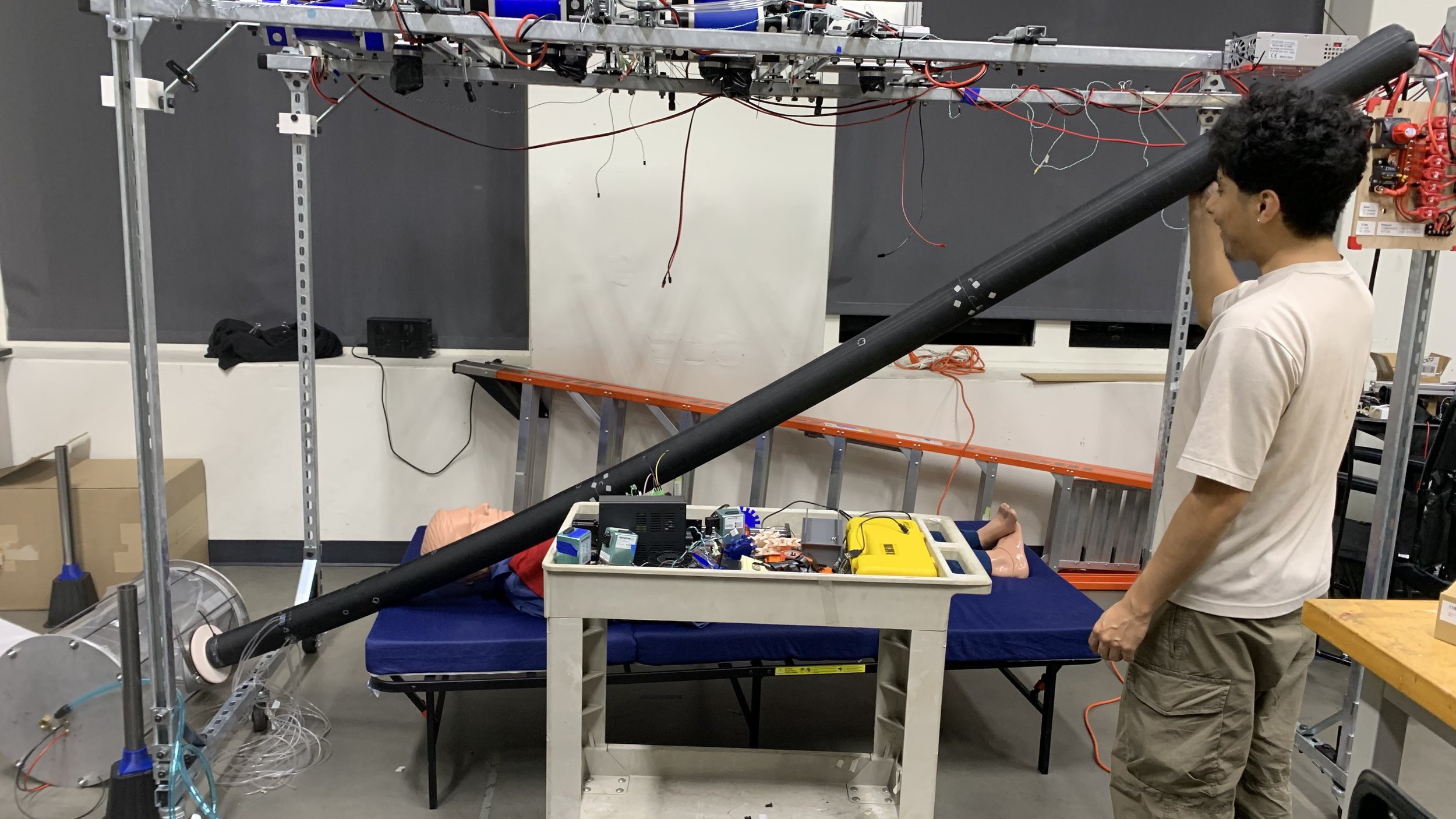
Our task was to improve the base station, the housing, for a vine robot and meet the given list of design requirements. The overarching goal was to improve the user experience and interaction with the robot. everything you need to know about vine robots
2024
Starting over
Our team’s task this summer was to improve on the previous iteration of the vine robot base station. The overarching theme was to have a good user experience. Some of the problems the current base station have are: end caps would blow off before reaching the operational pressure, internals are difficult to access, vine robot body would tangle during use, fabric catches onto grommet
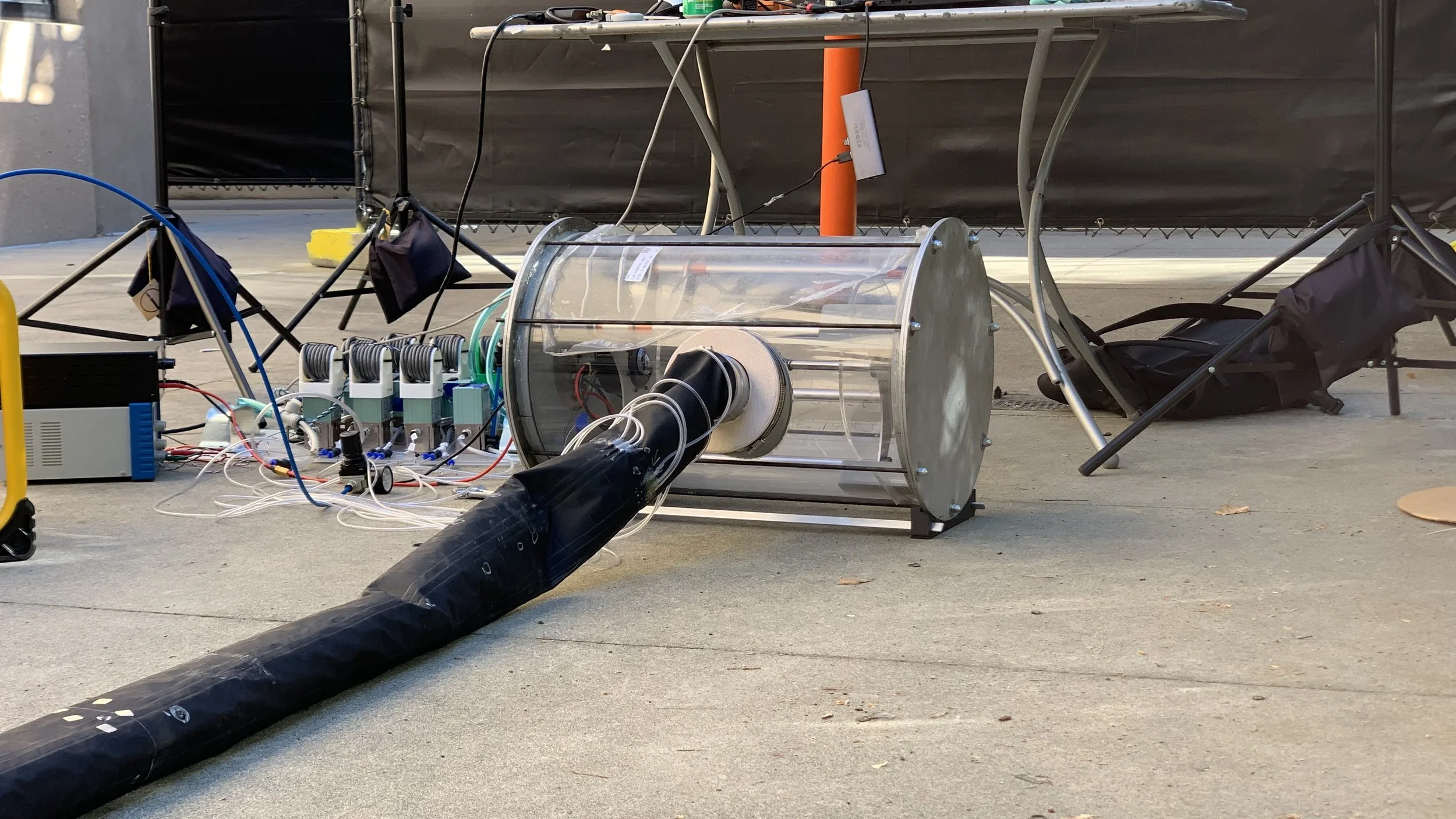
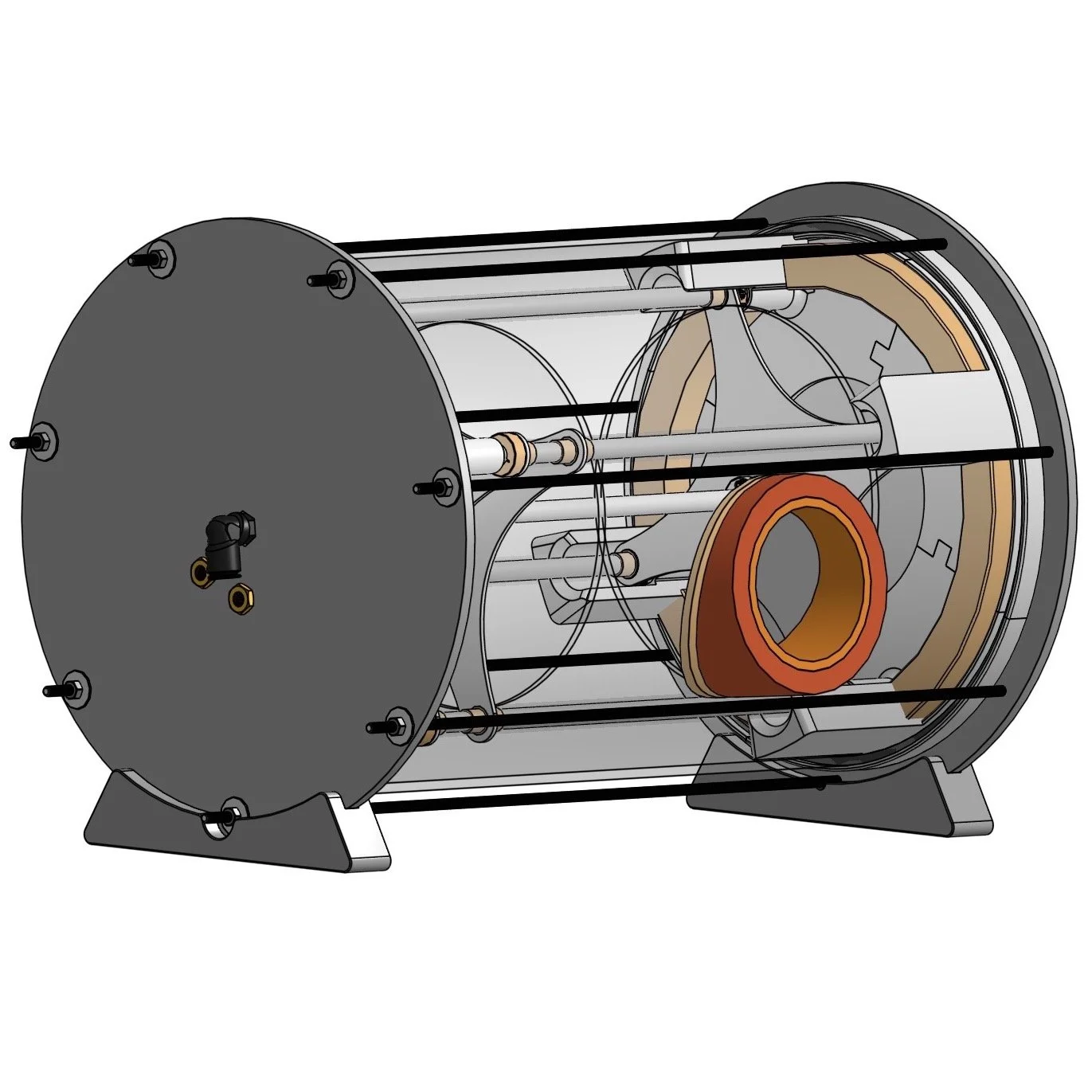
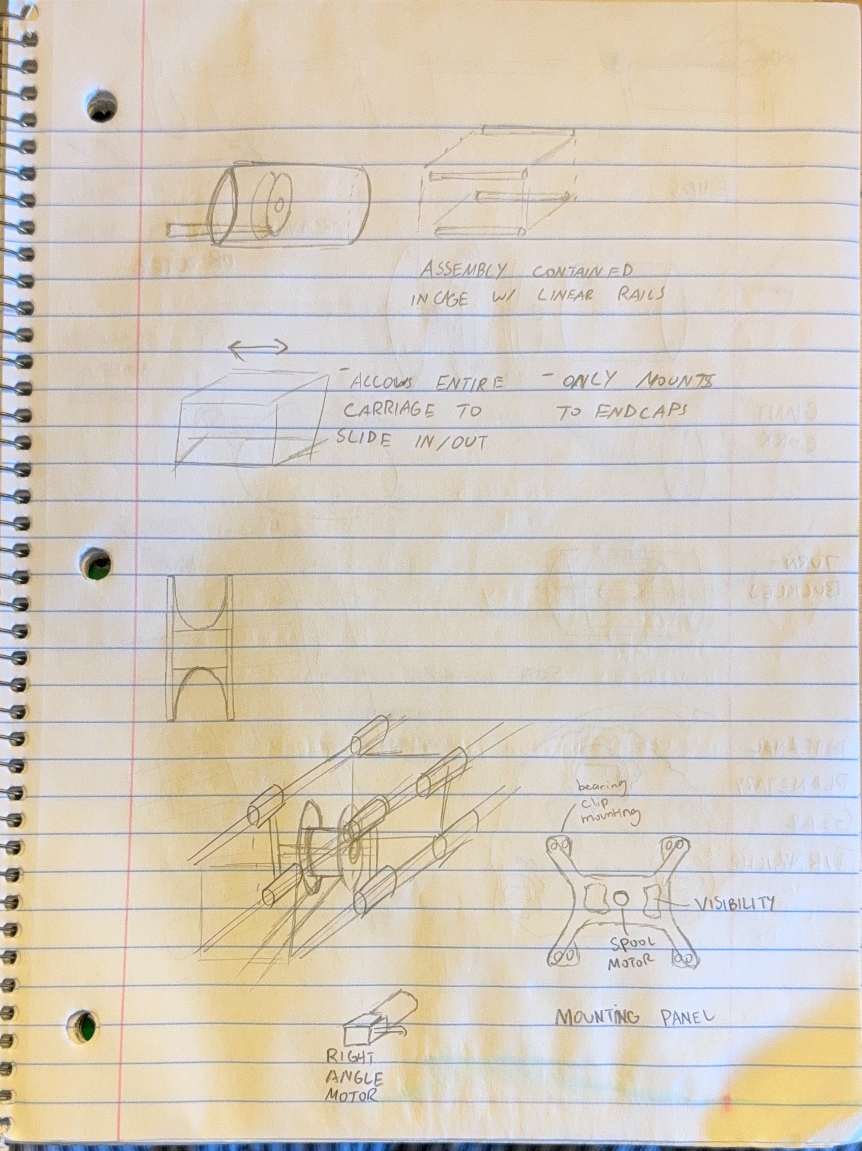
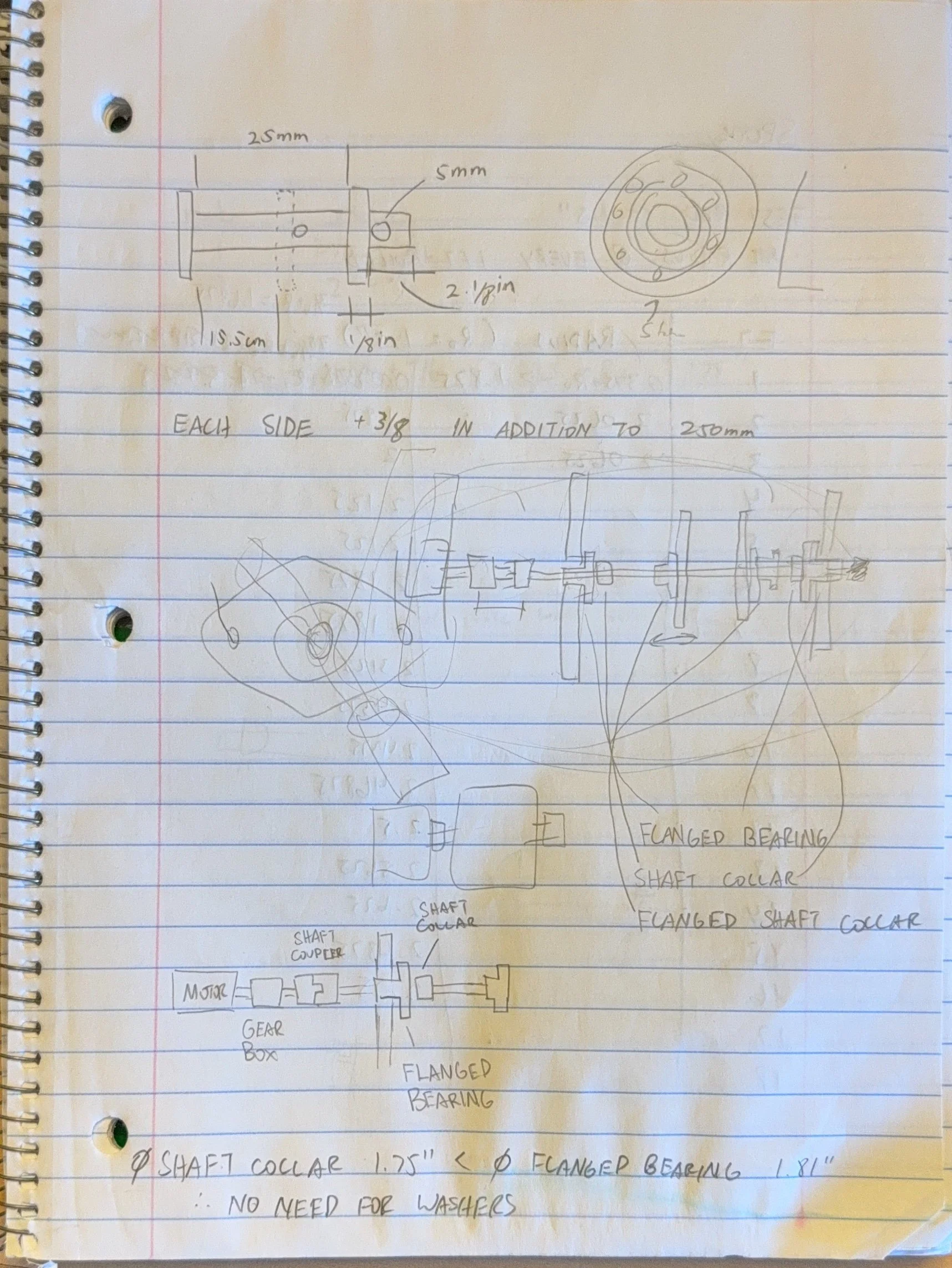
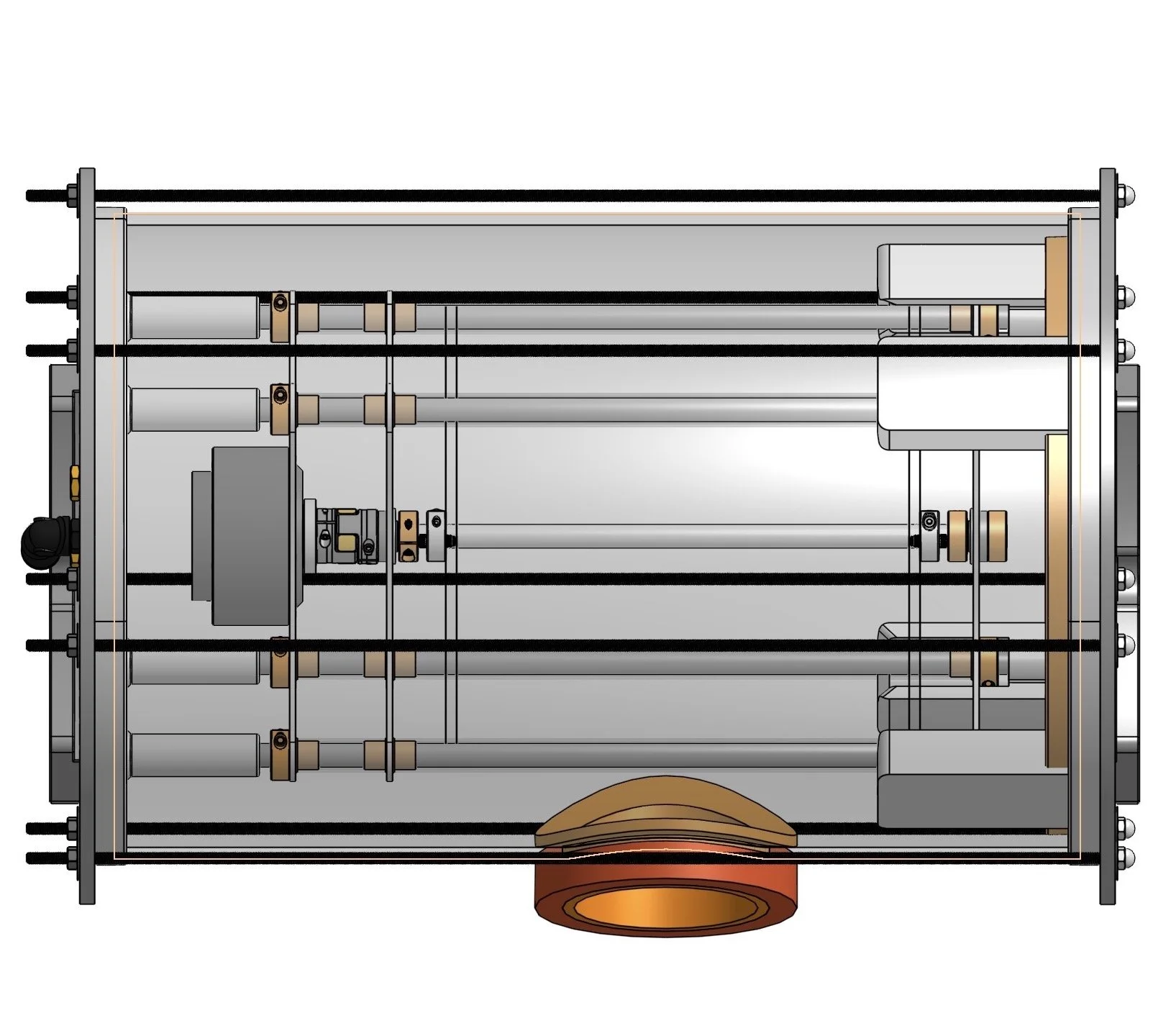
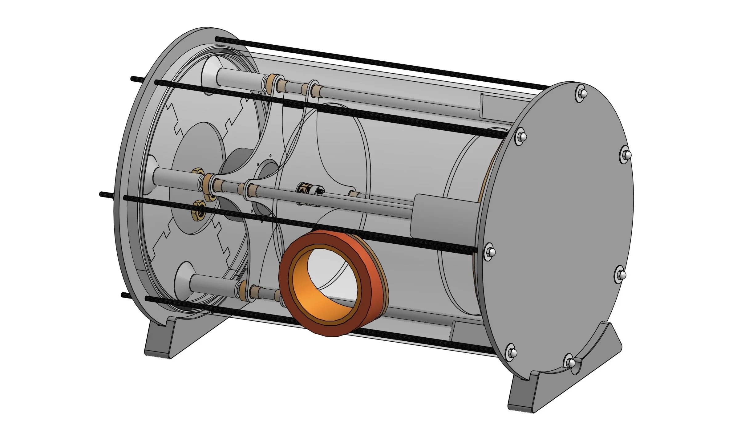
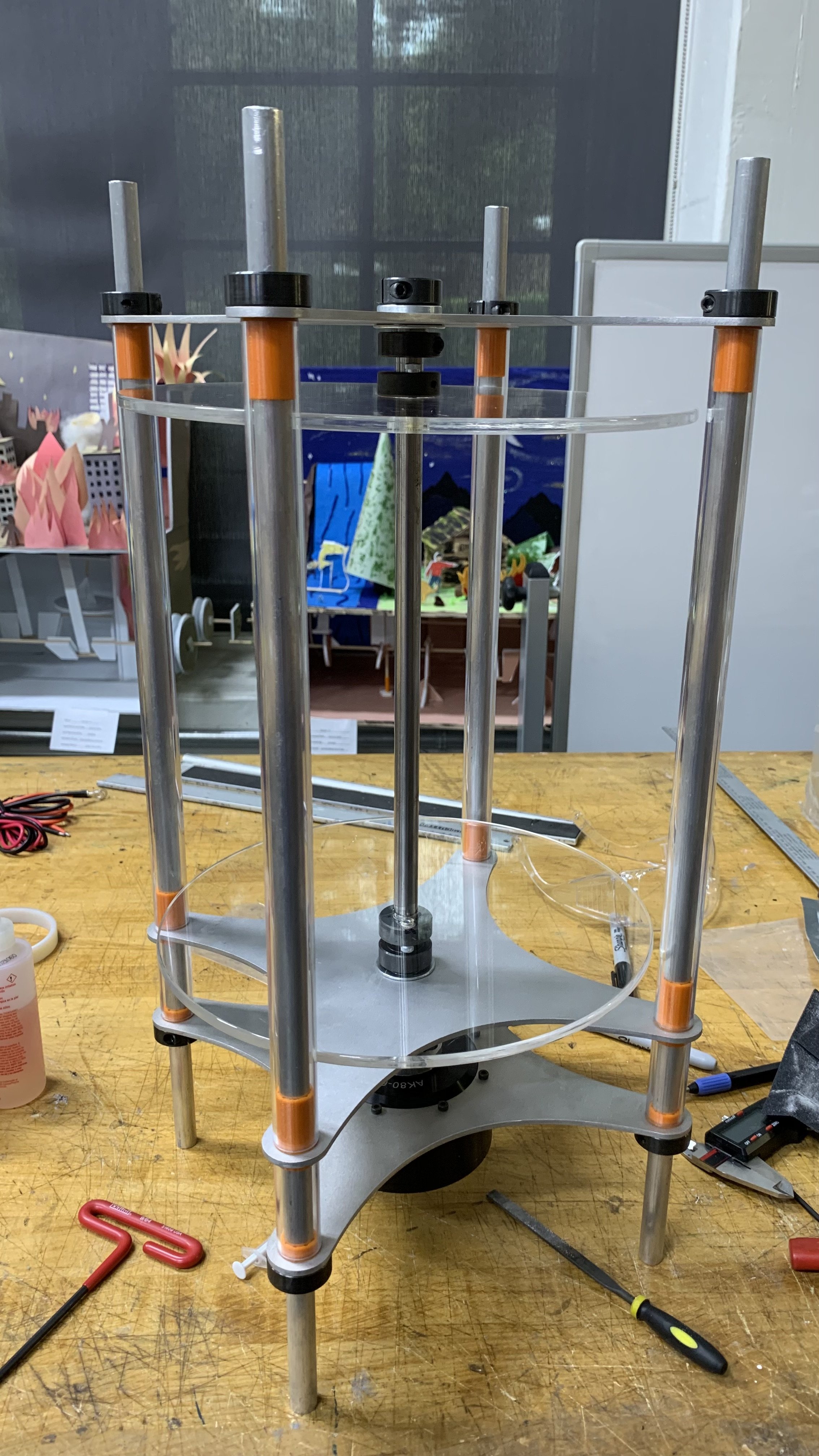
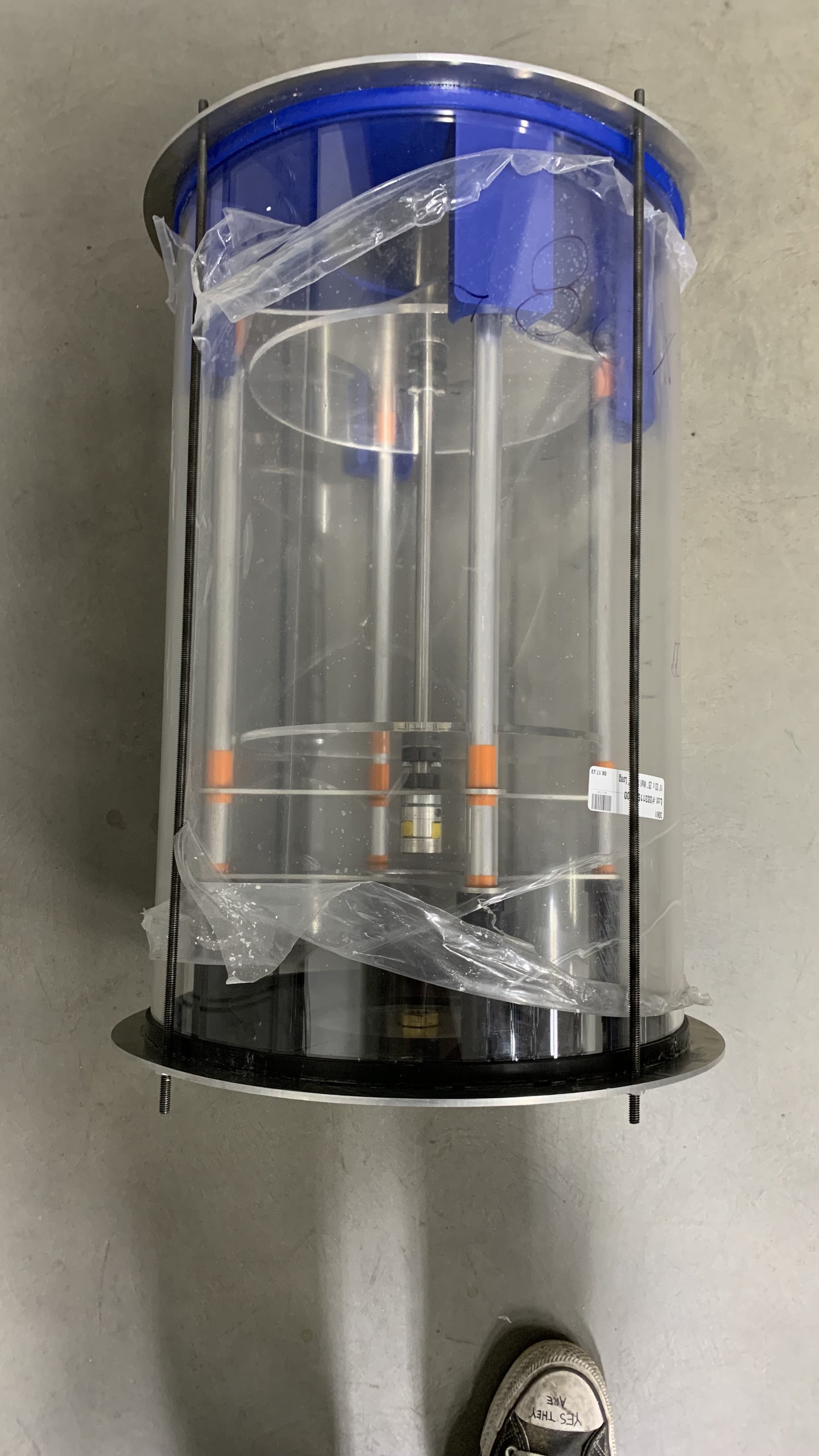
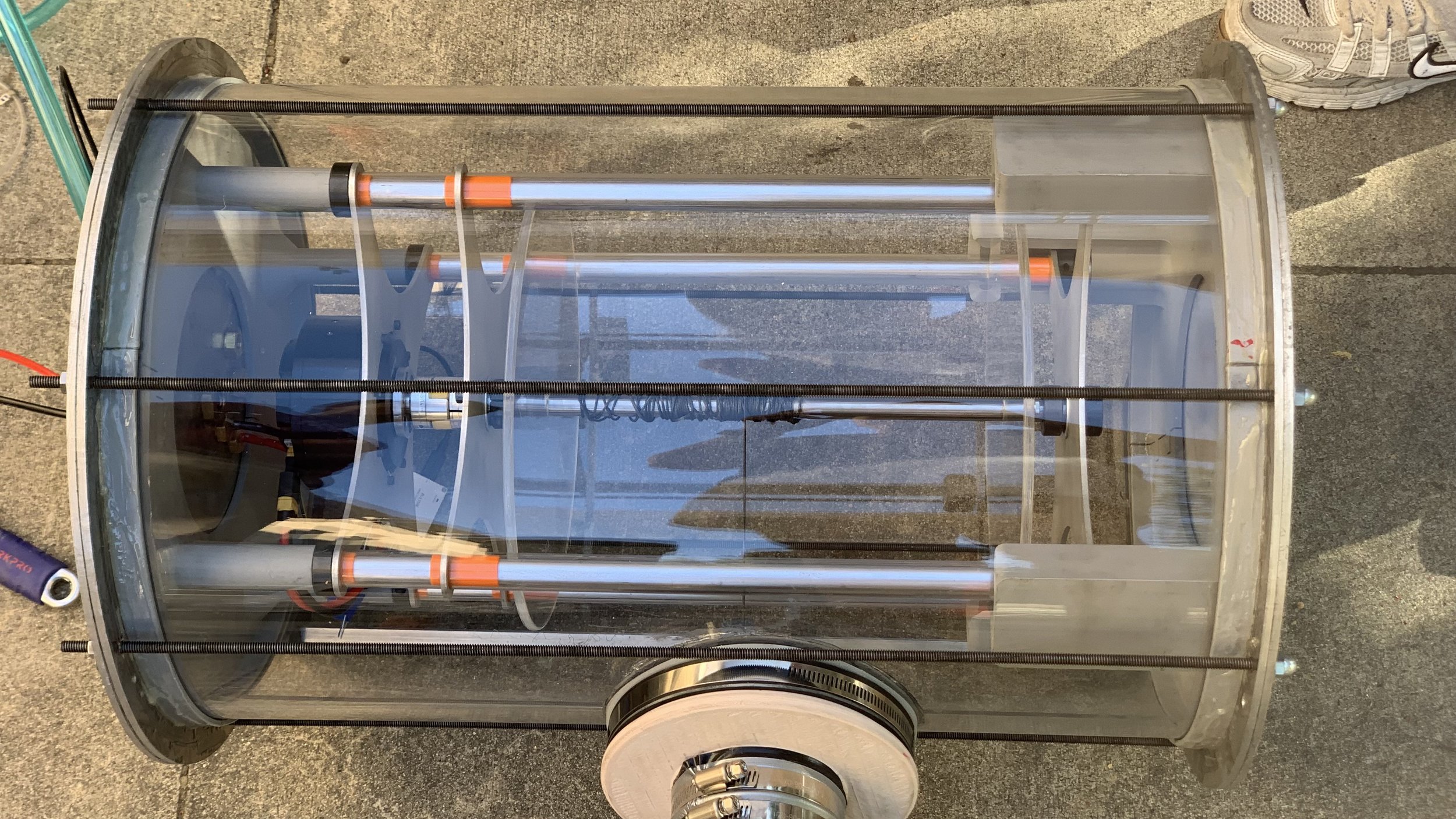
We came up with an exciting idea of mounting all internal components on a carriage system similar to a drawer in a cabinet. This will allow future adjustments, modifications, and upgrades to components. It will be contained in an acrylic cylinder allowing clear visibility to the internals during operation and give the user peace of mind.
some details of the process and design may be left out due to confidentiality




CAD
We included all the components in CAD using onshape. It required a slight learning curve but was very efficient in terms of collaborating, sharing files, and bringing parts together to create the assembly.
Crucial proprietary parts were made in CAD then 3D printed due to complexity in manufacturing.

Spool characterization
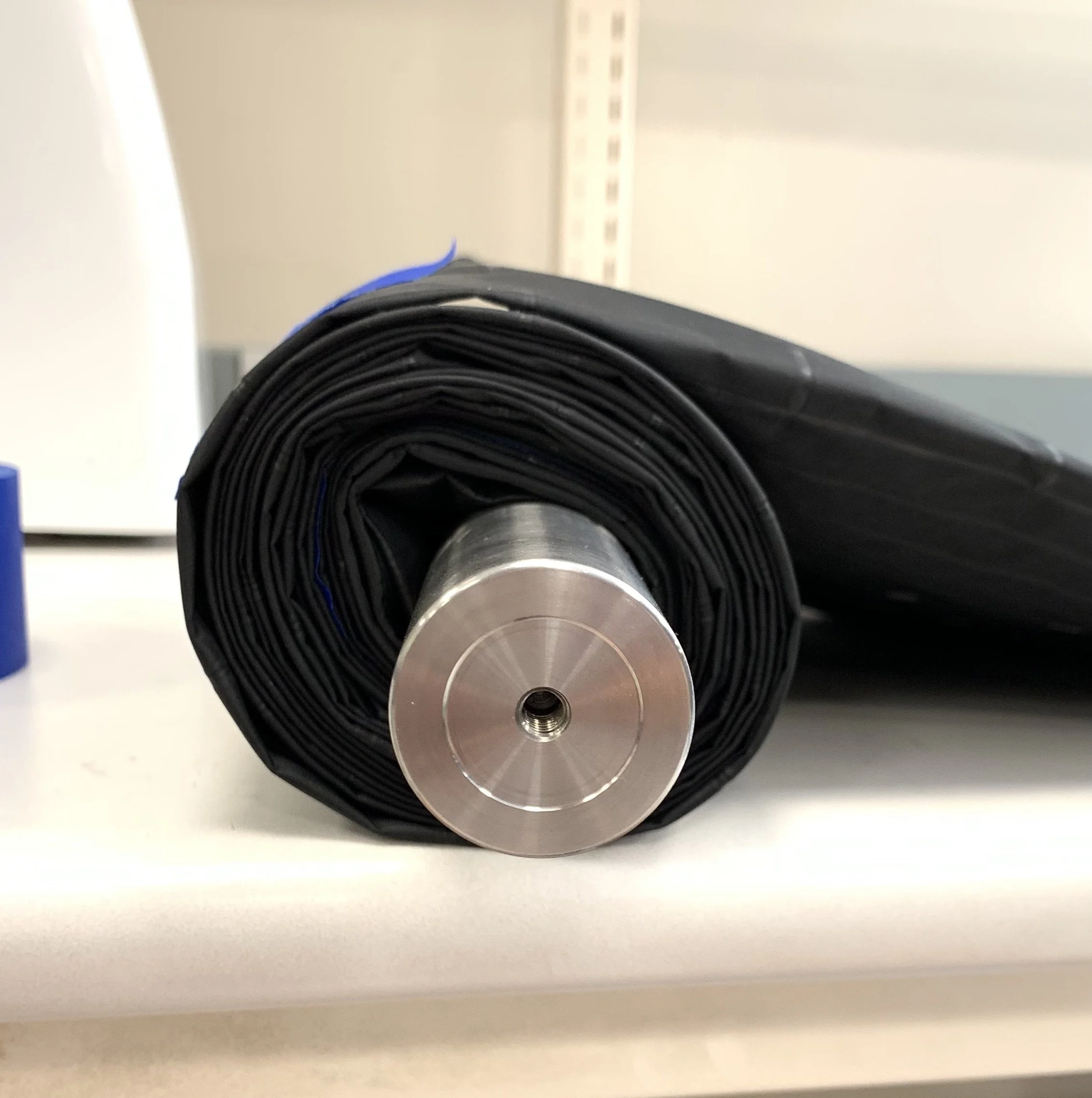
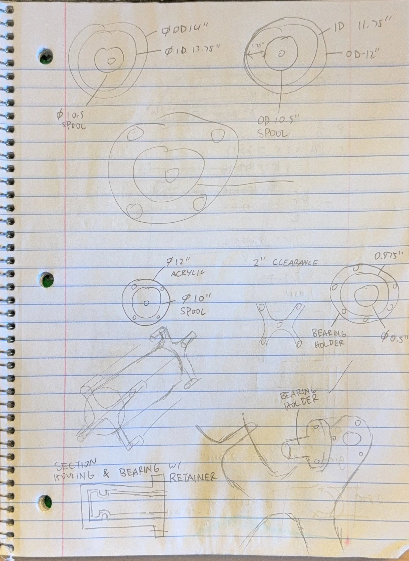
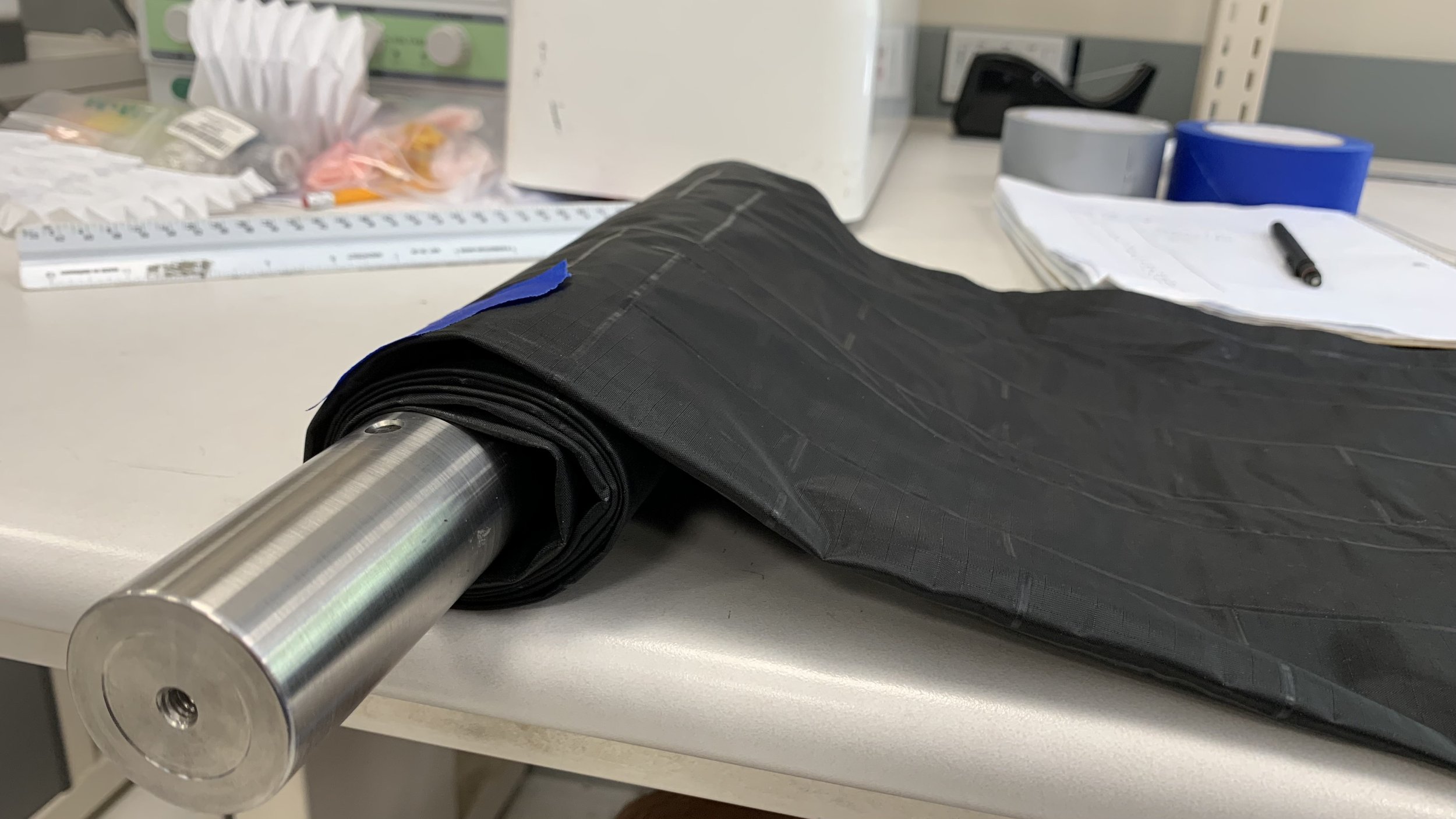
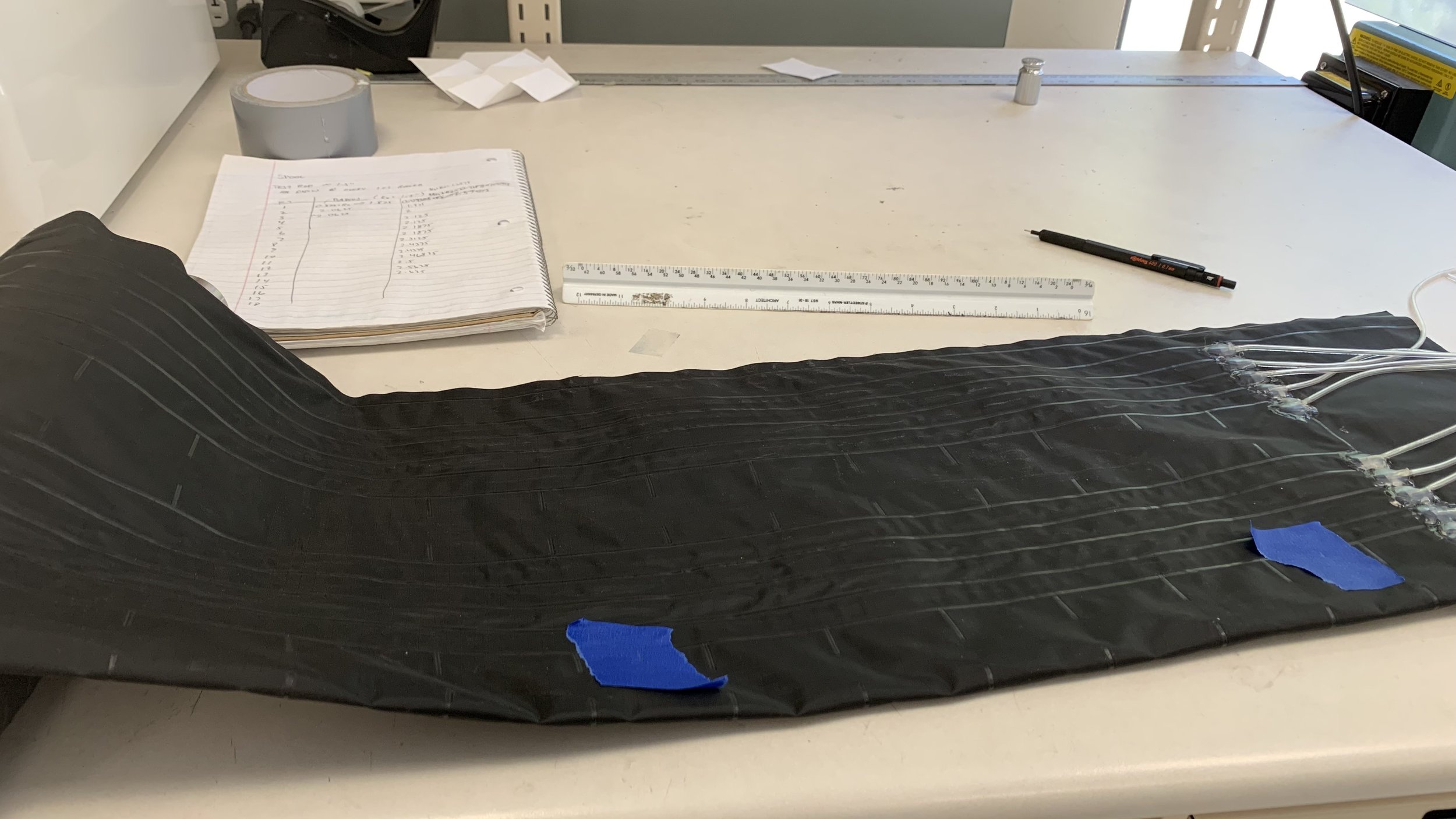
To get a sense of how big the spool sidewalls, carriage system, and therefore base station is, the diameter was characterized by my teammate Sal. The vine robot was wounded on a half inch axle and data points were collected at multiple layers.
System sidewalls and endcaps
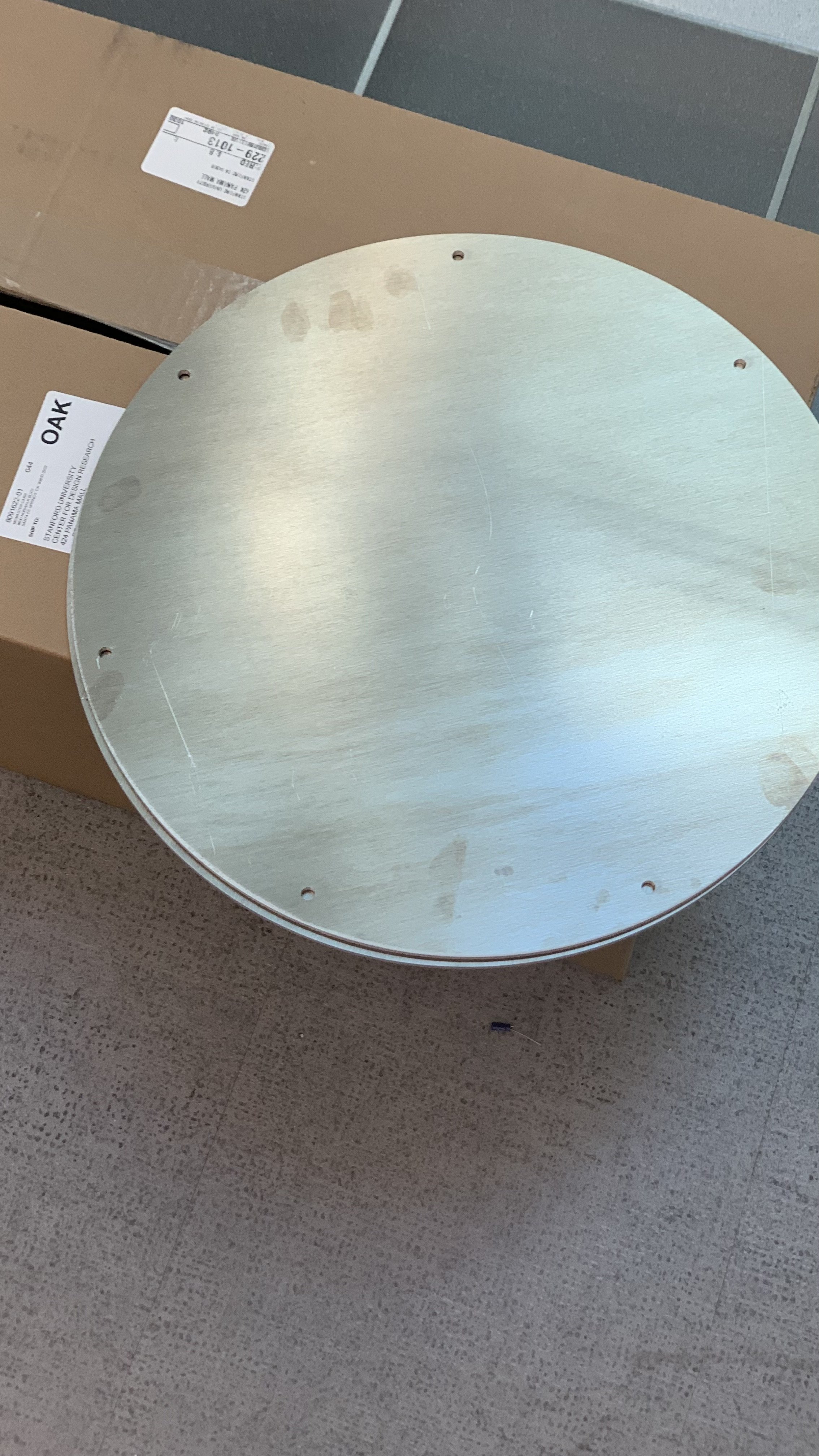
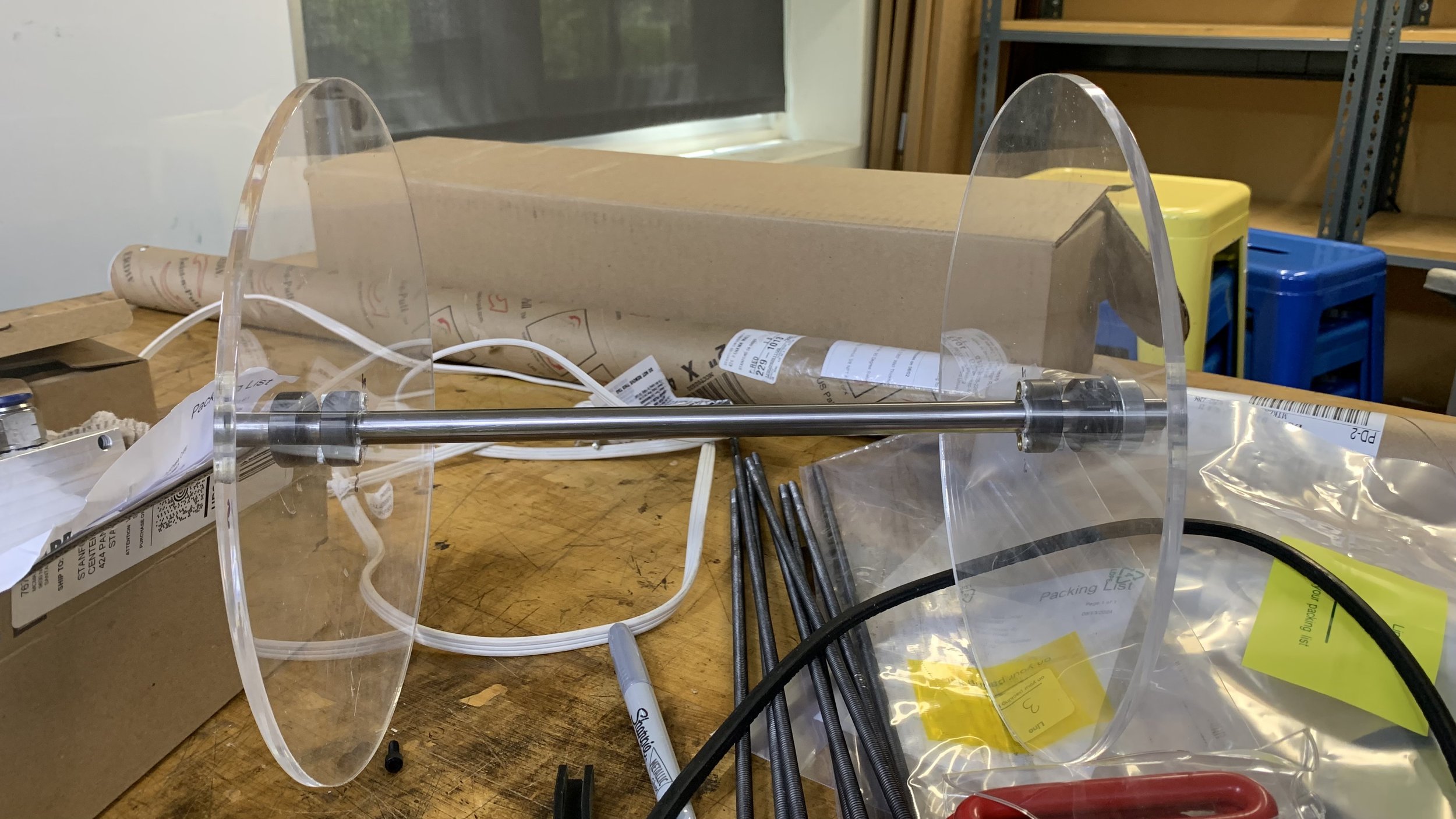
There are two kinds of sidewalls used: spool sidewalls to contain the vine robot’s body and carriage sidewalls to mount all internal components to.
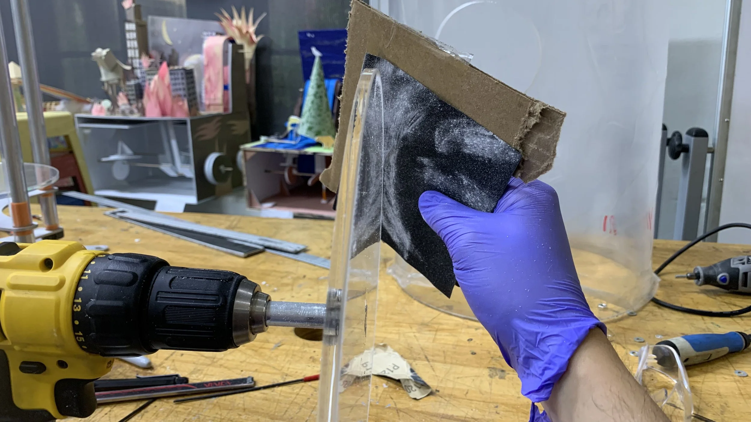
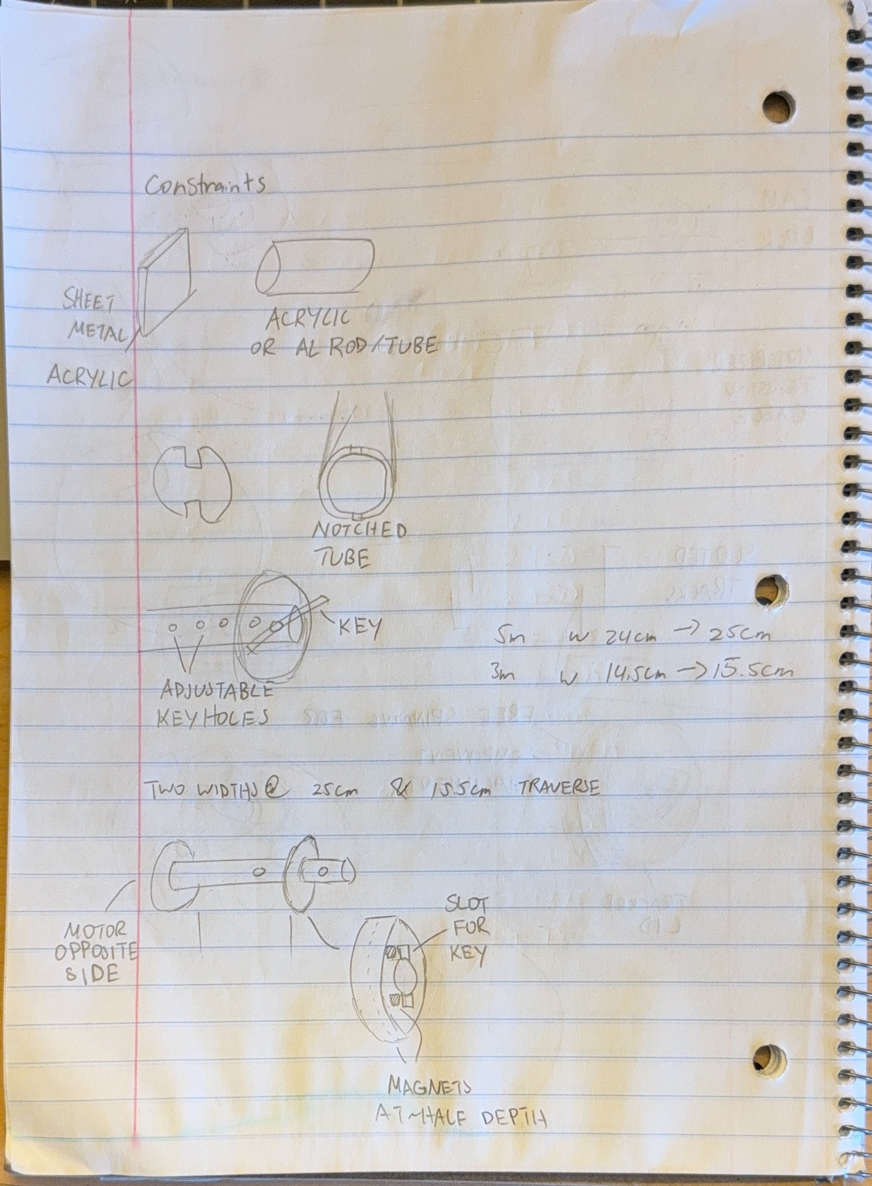
The former is made with laser cut acrylic. A threaded insert was added in order to join it to a shaft collar. Smooth fillets were given to the edges to prevent the off chance that the fabric slides and rubs against it.
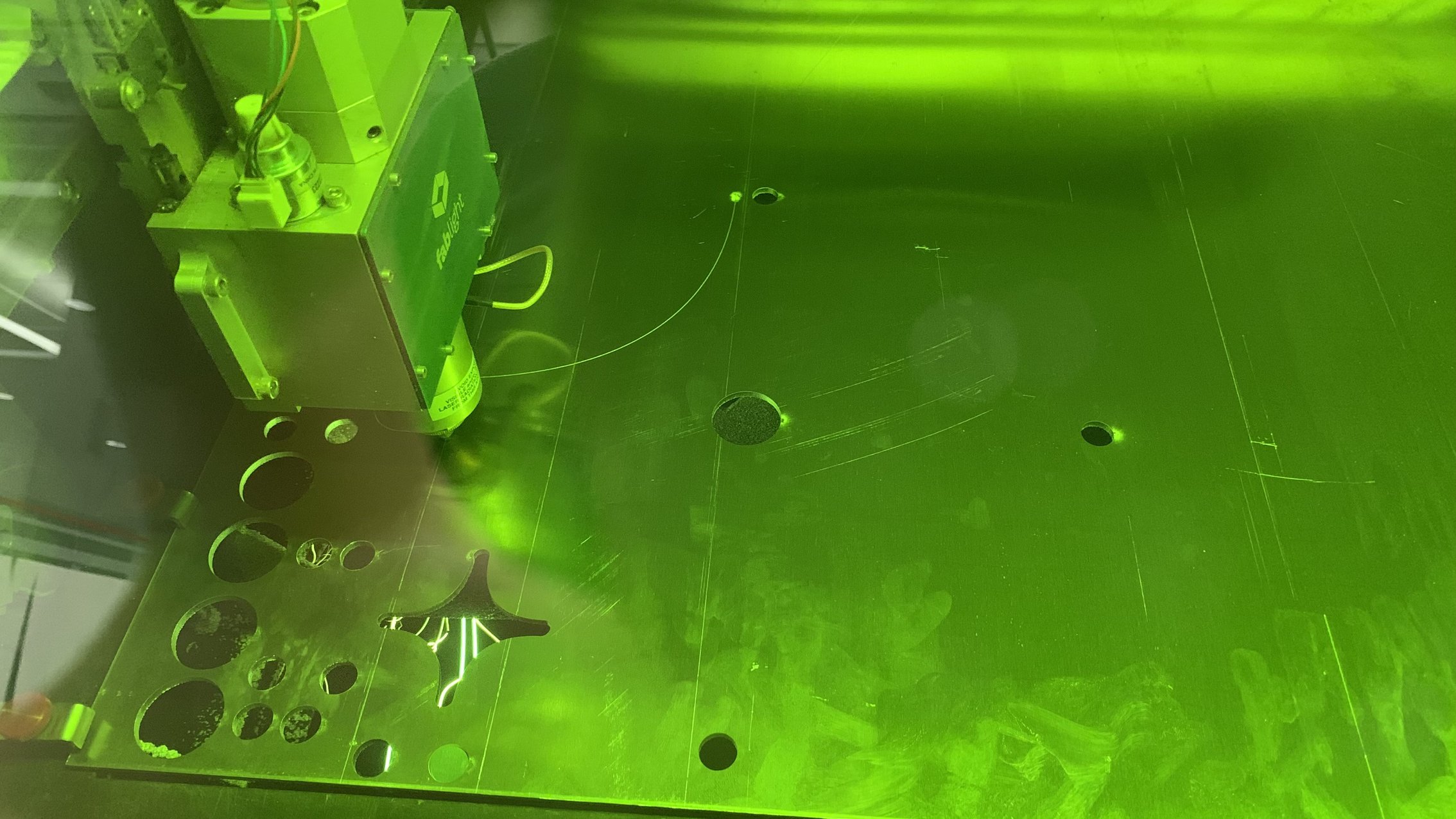
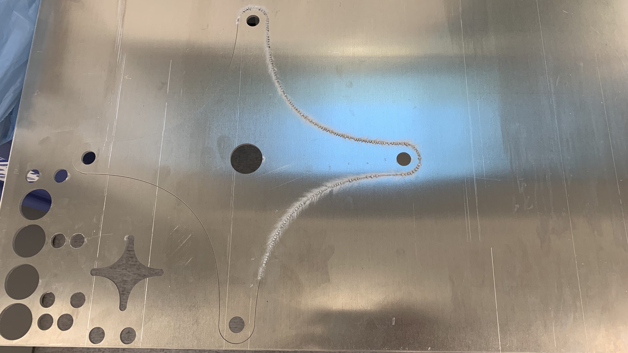
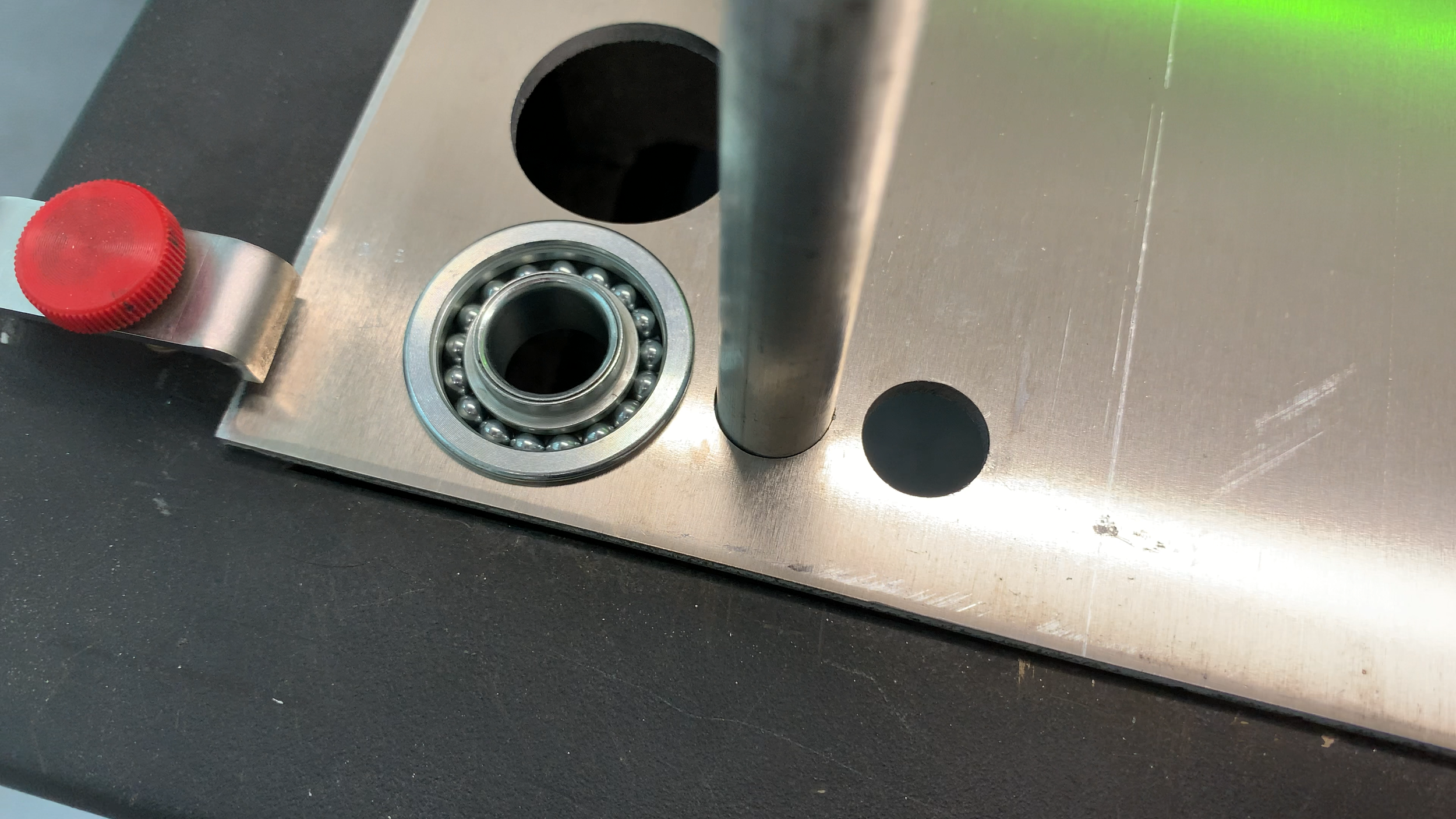
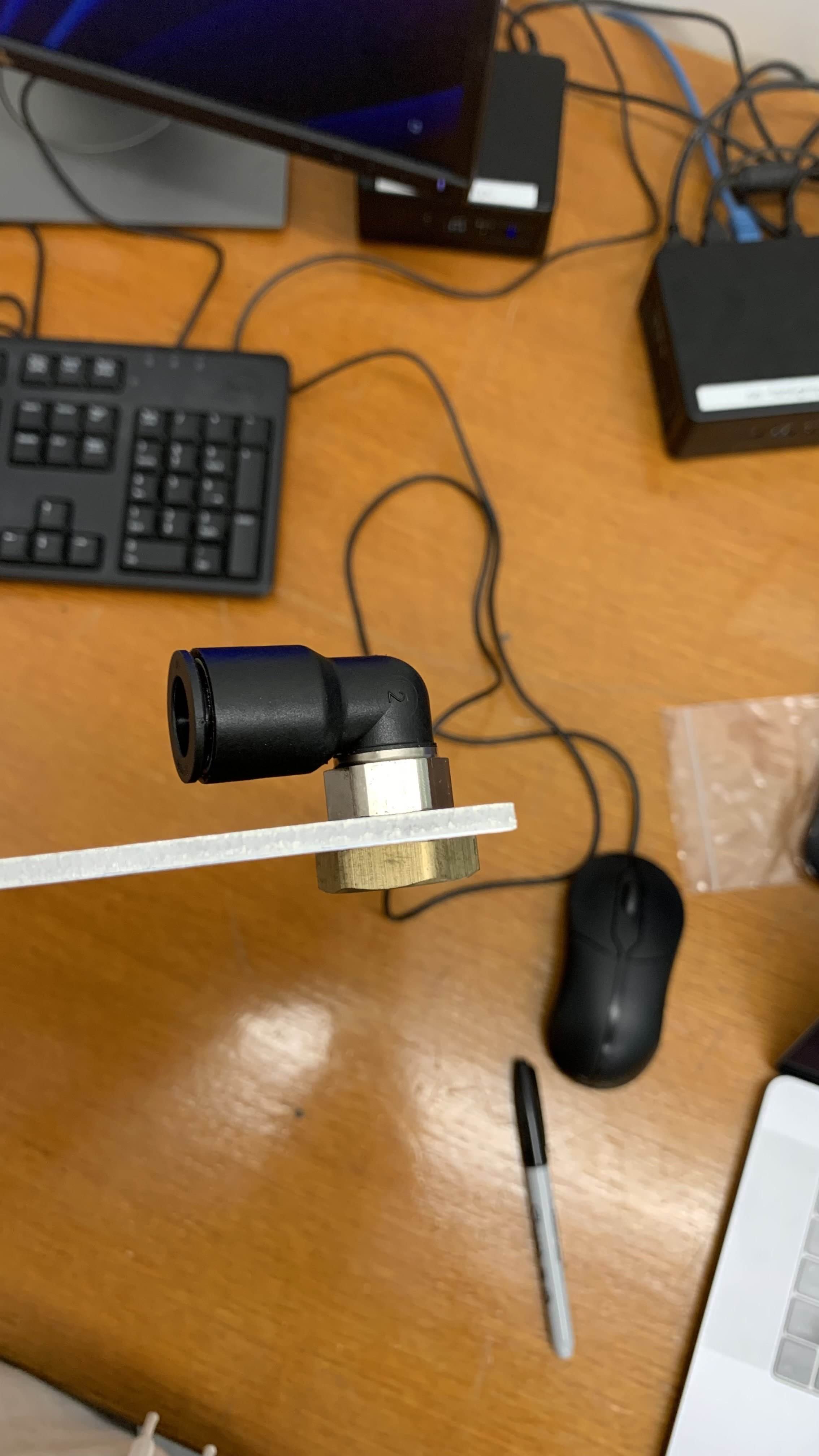
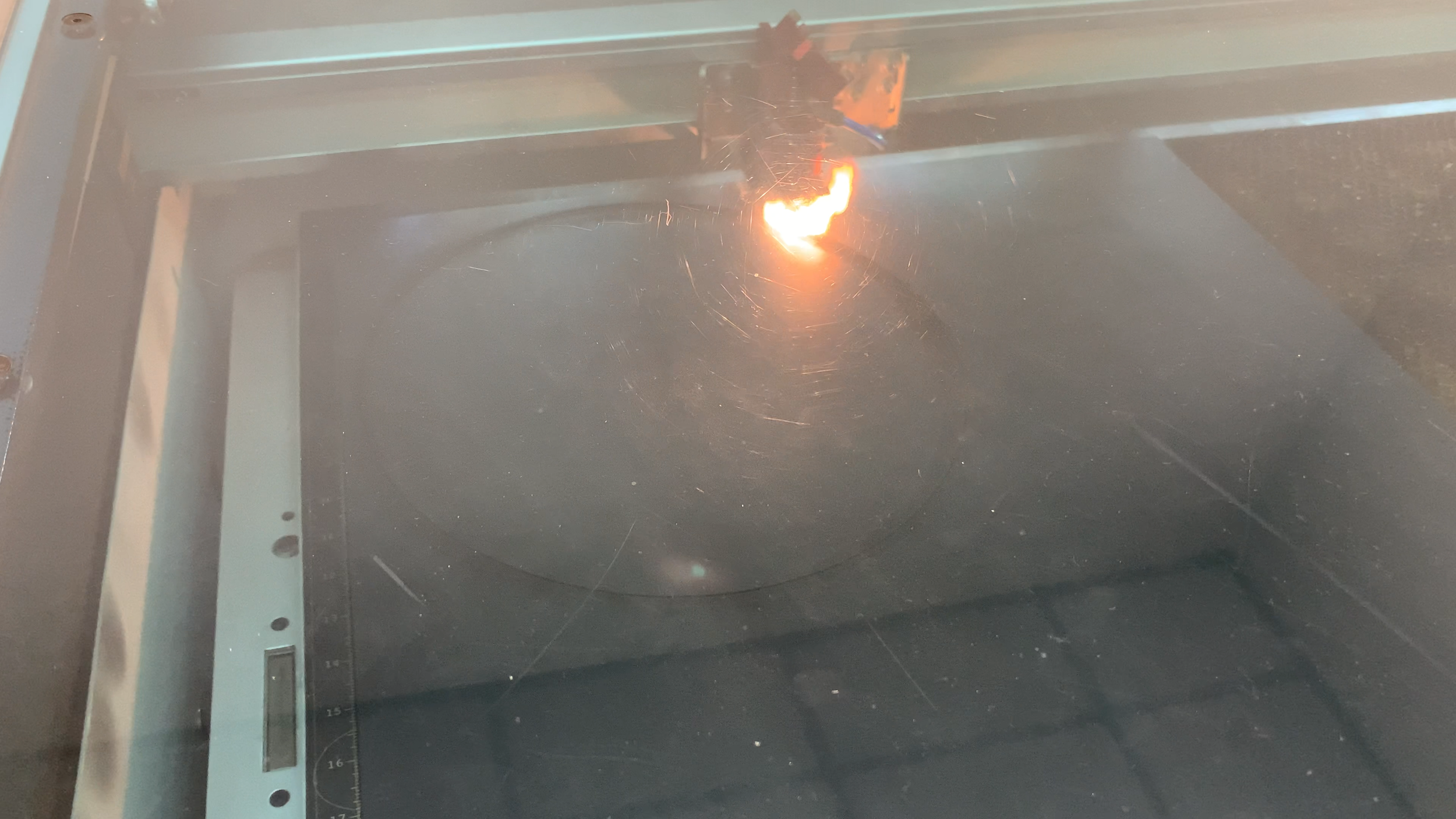
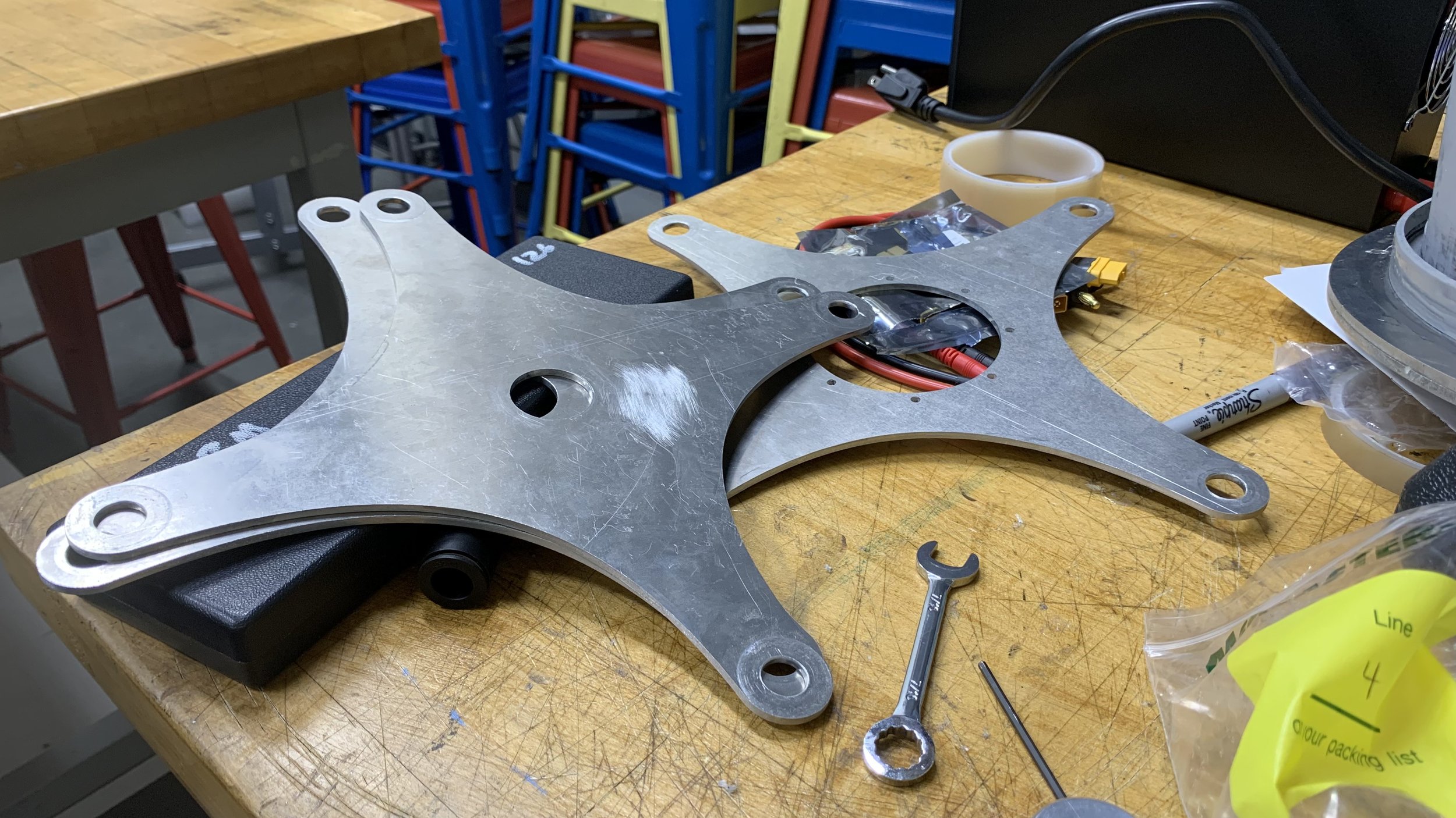
The latter was made with laser cut aluminum. Test clearance holes were created to find the optimal size for fit as well as decrease the amount of rattling the system may encounter. An issue encountered was pressure drop of the laser cutter, which prevented the laser from penetrating the metal. The end caps of the system were also made with the laser cutter. We also had to find the optimal hole size to make sure the screw and nut fittings for data wires and air supply won’t leak.
Sealing troubles
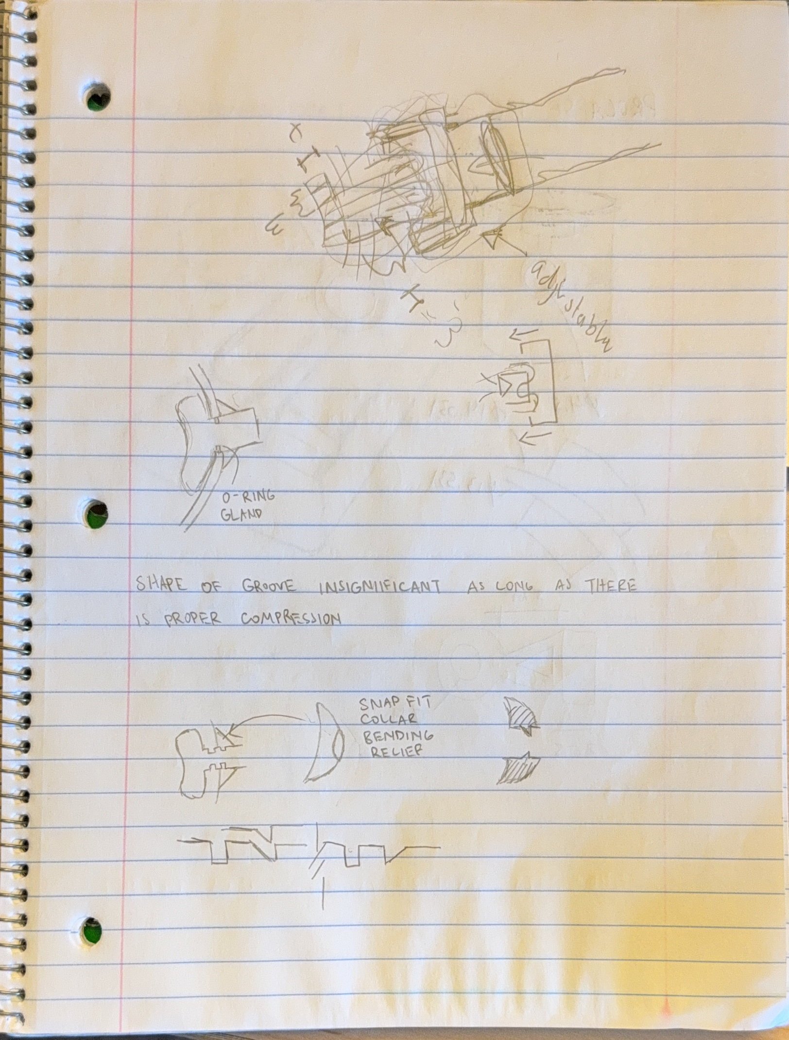
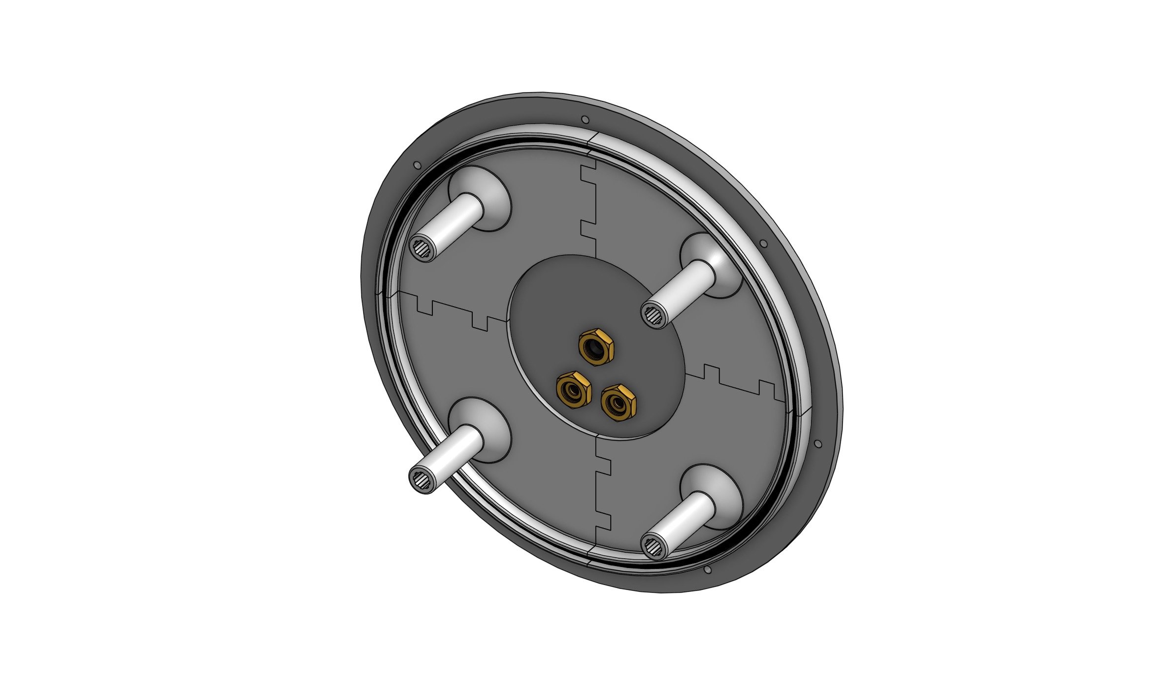
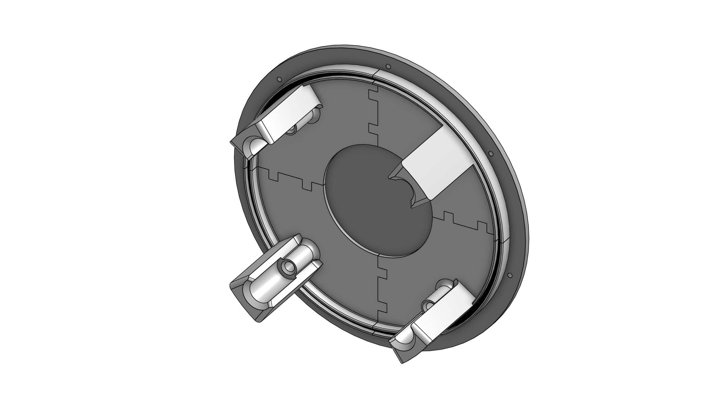
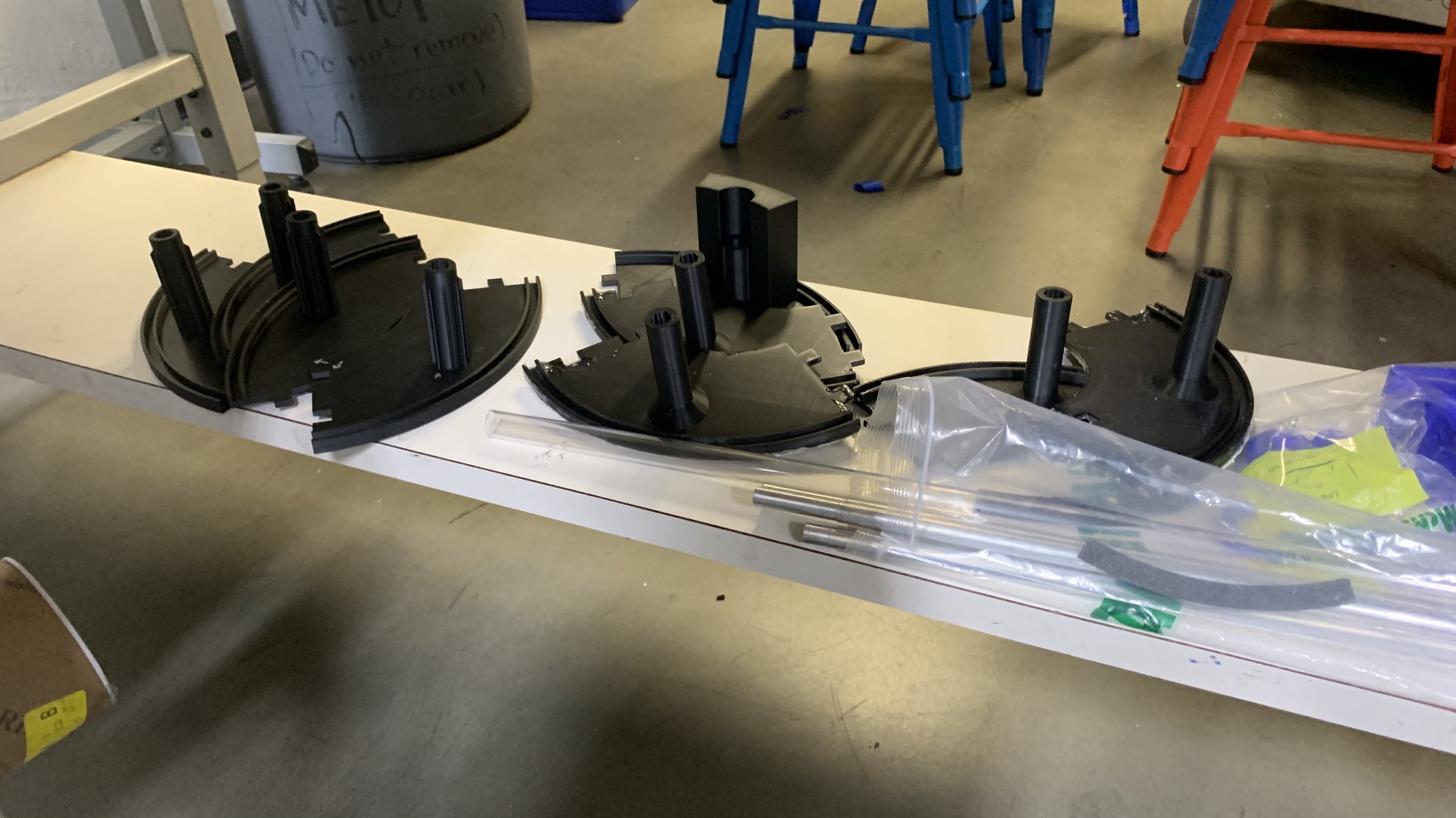
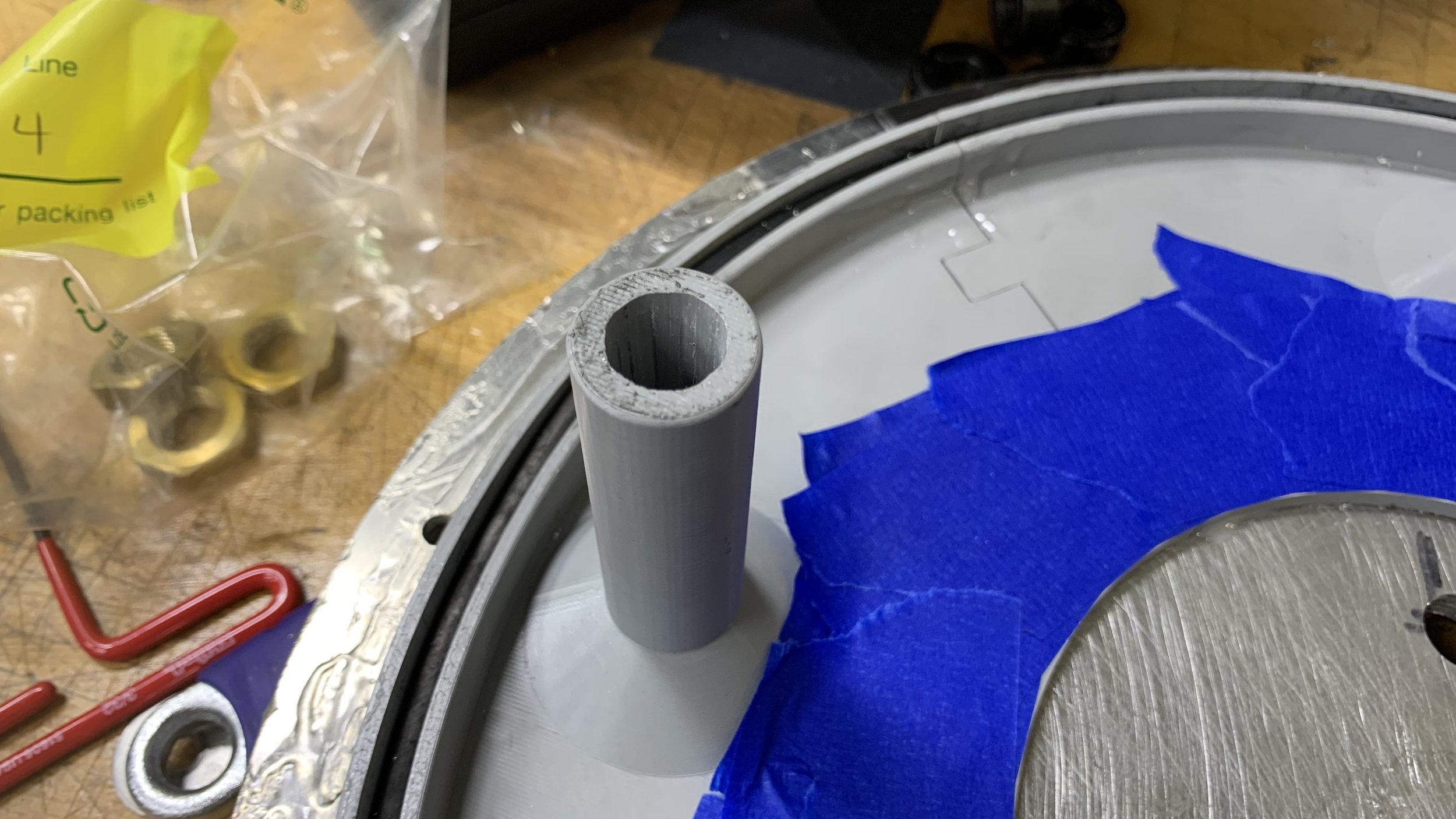
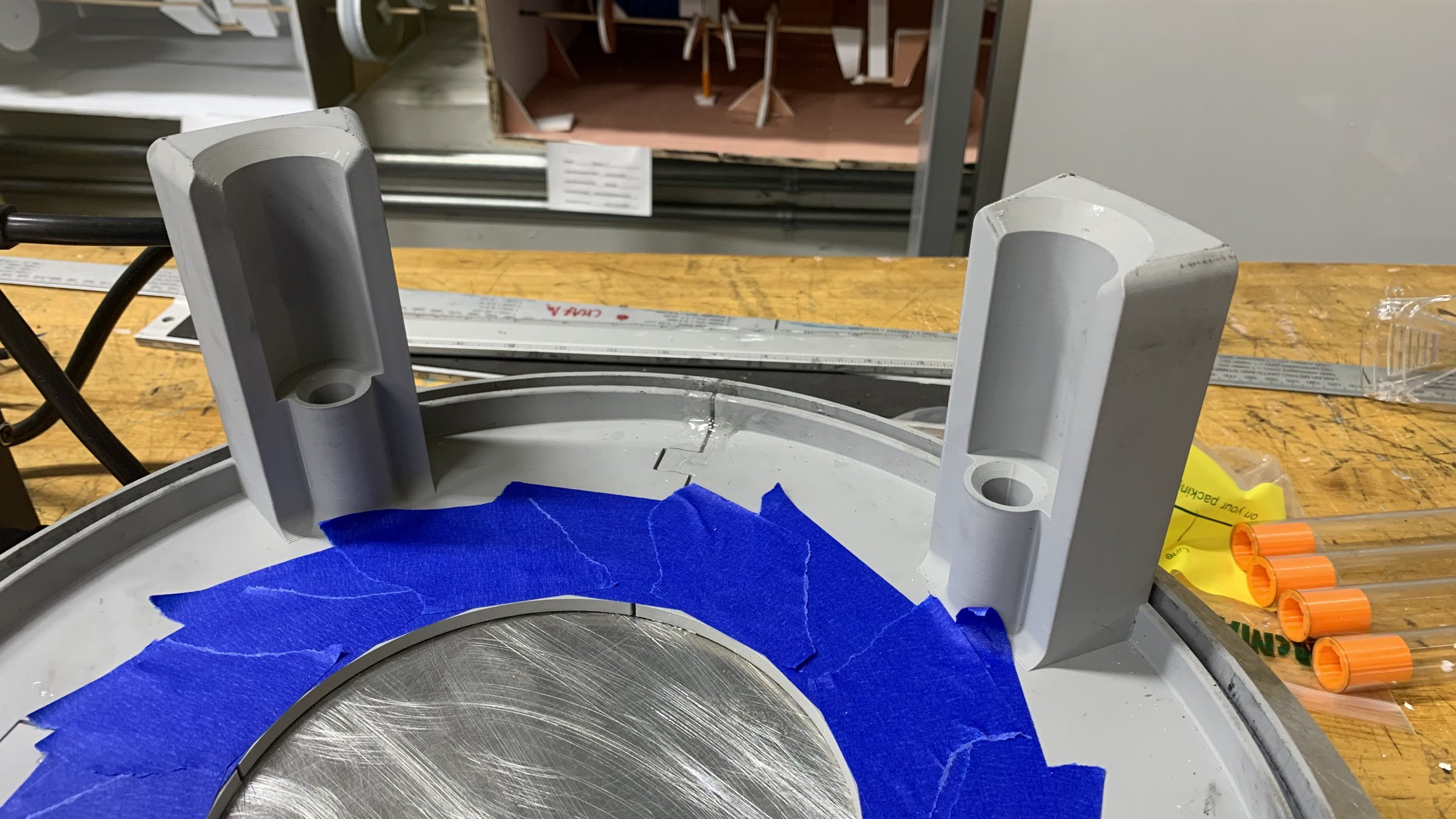
The 3D printed parts that acted as shoulders for the carriage system had to be separated into 4 due to the bed size constraint of the 3D printers, therefore they had jigsaw puzzle tongue & groove features to piece together. The groove where the acrylic cylinder sits in has a large nitrile gasket that was laser cut. The prints were then epoxied onto the aluminum end caps for pressure testing. However, the seams of the prints as well as the warping of the end caps caused by uneven tightening revealed a lot of gaps. The solution was to add a second layer on each side of the end caps and epoxy where necessary.
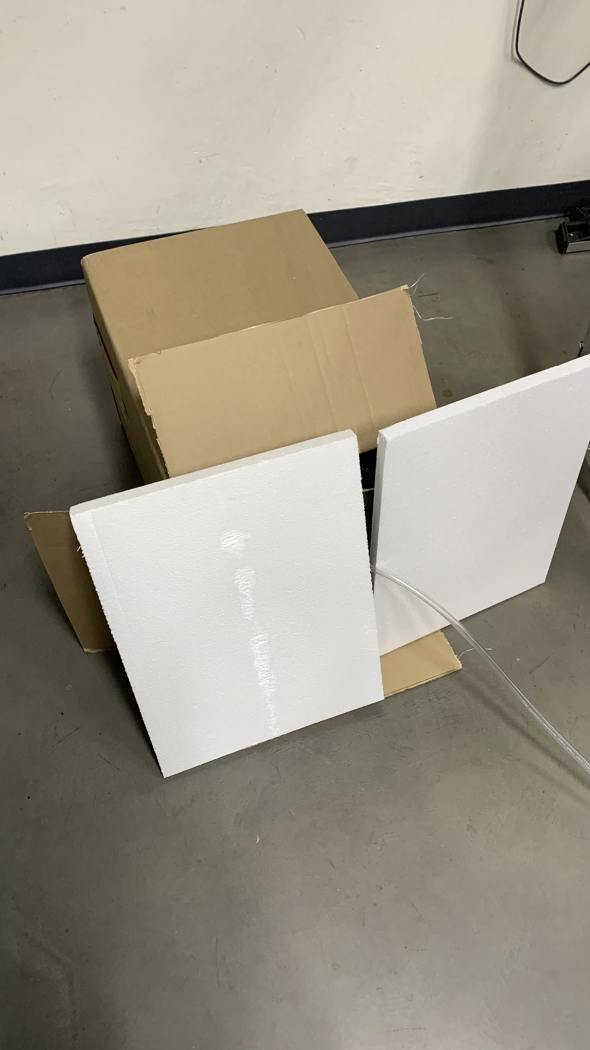
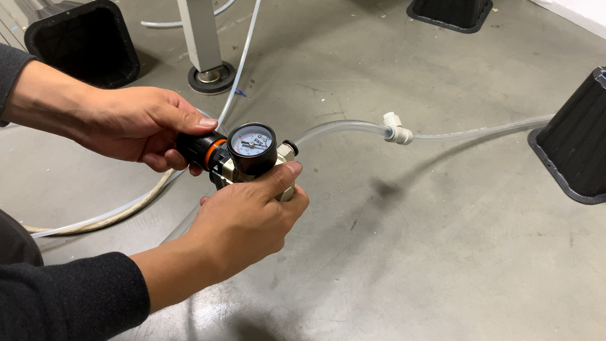
The photo on the left shows a pressure test with the base station barricaded in a cardboard box with impenetrable styrofoam doors.


Carriage assembly
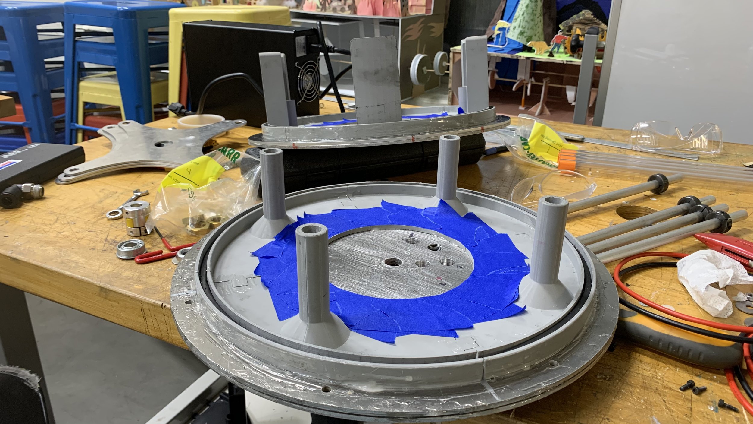
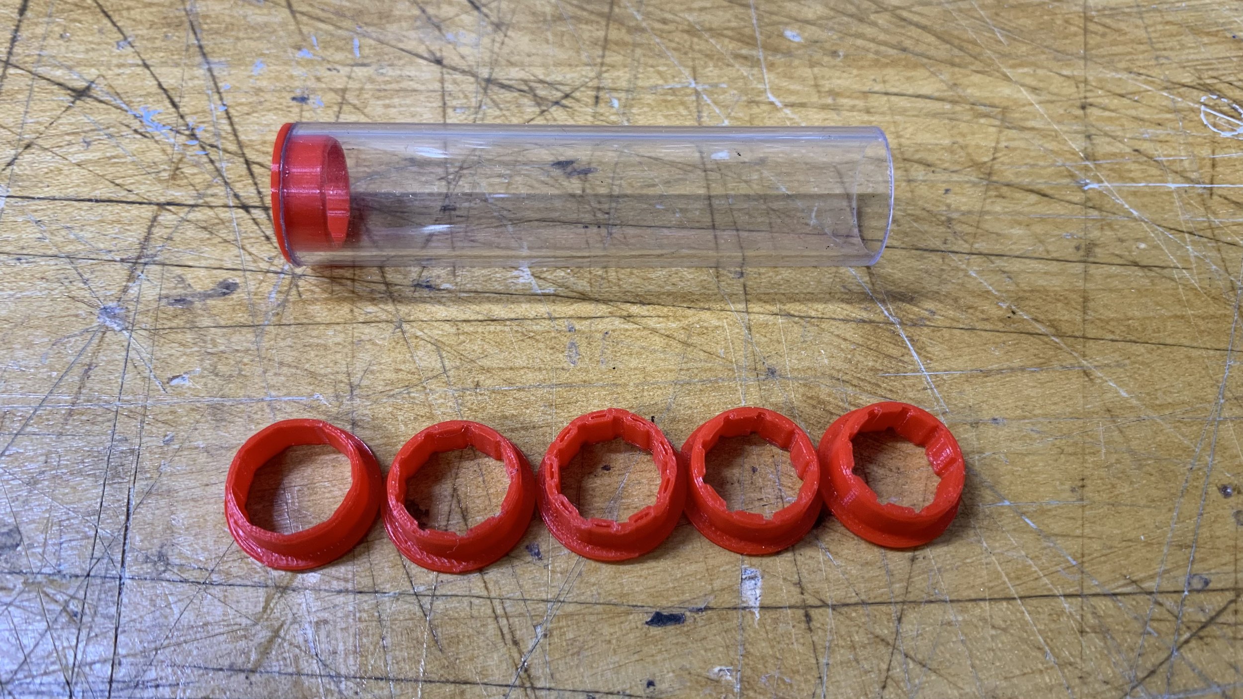
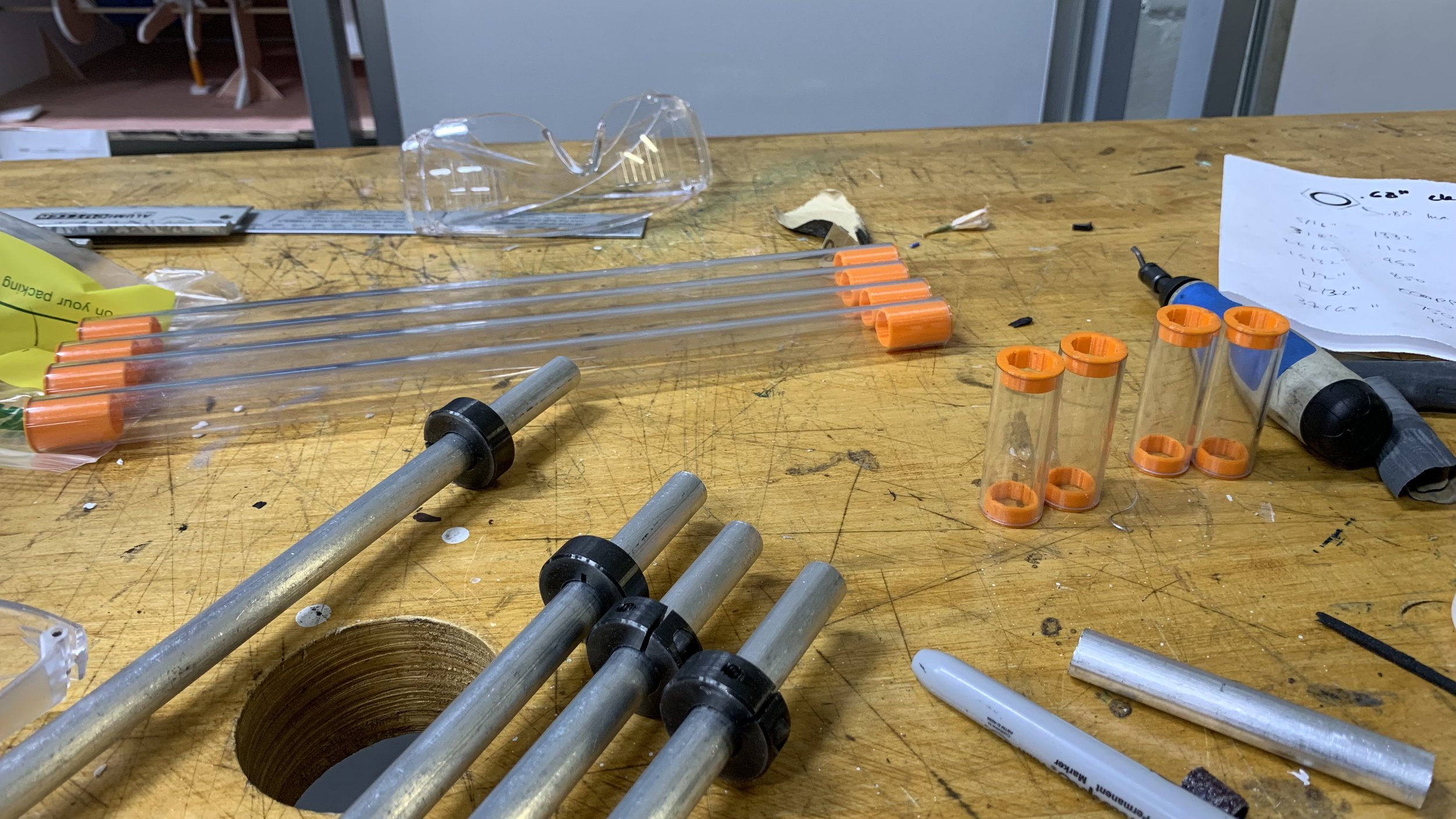
In order to space the components on the carriage and therefore the distance between sidewalls, acrylic tube spacers were used. However, they had to be one size up from the OD of the aluminum rods as it would require a press fit, which was risky in terms of assembly/disassembly. This would cause a lot of rattling as the acrylic spacers were free to move around. To fix this, spacer caps were made with air vents to prevent it from popping off during assembly (similar to a pen cap design).
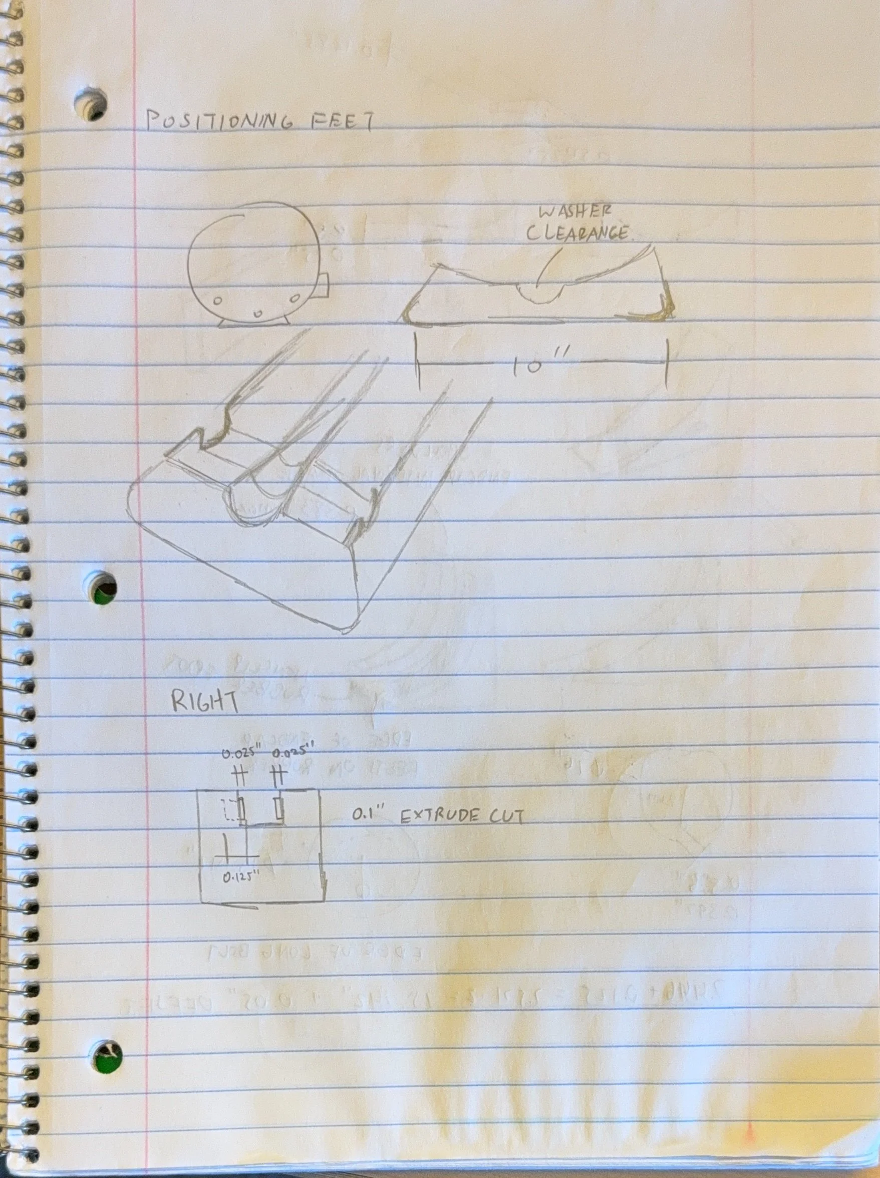
The 3D printed parts have 2 variations: one side where the carriage is fixed to end cap so the user can slide the entirety out. The other side has guides with oversized chamfers such that the user can slide the carriage into with ease and requires no effort in lining it up.
The hole jig
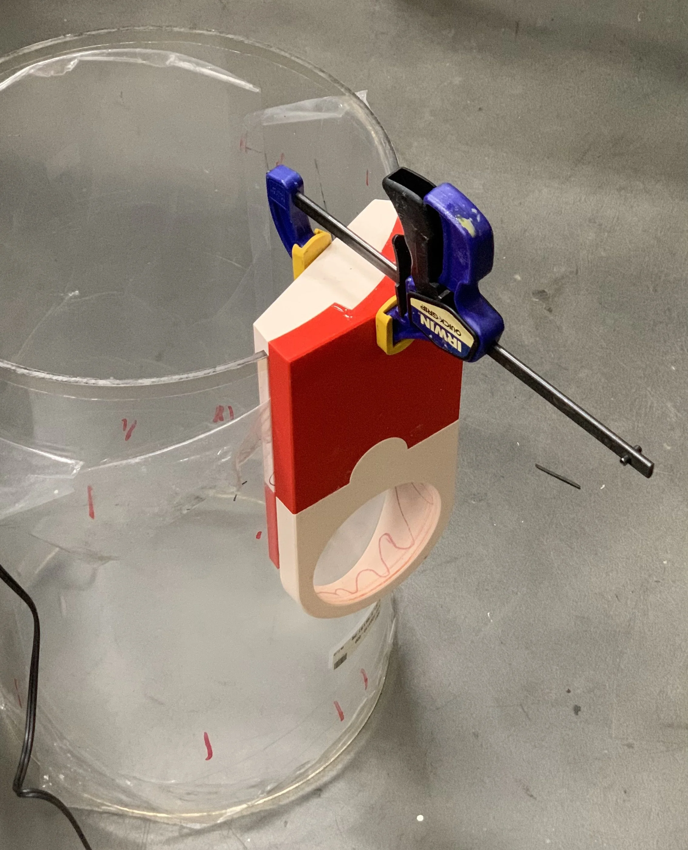
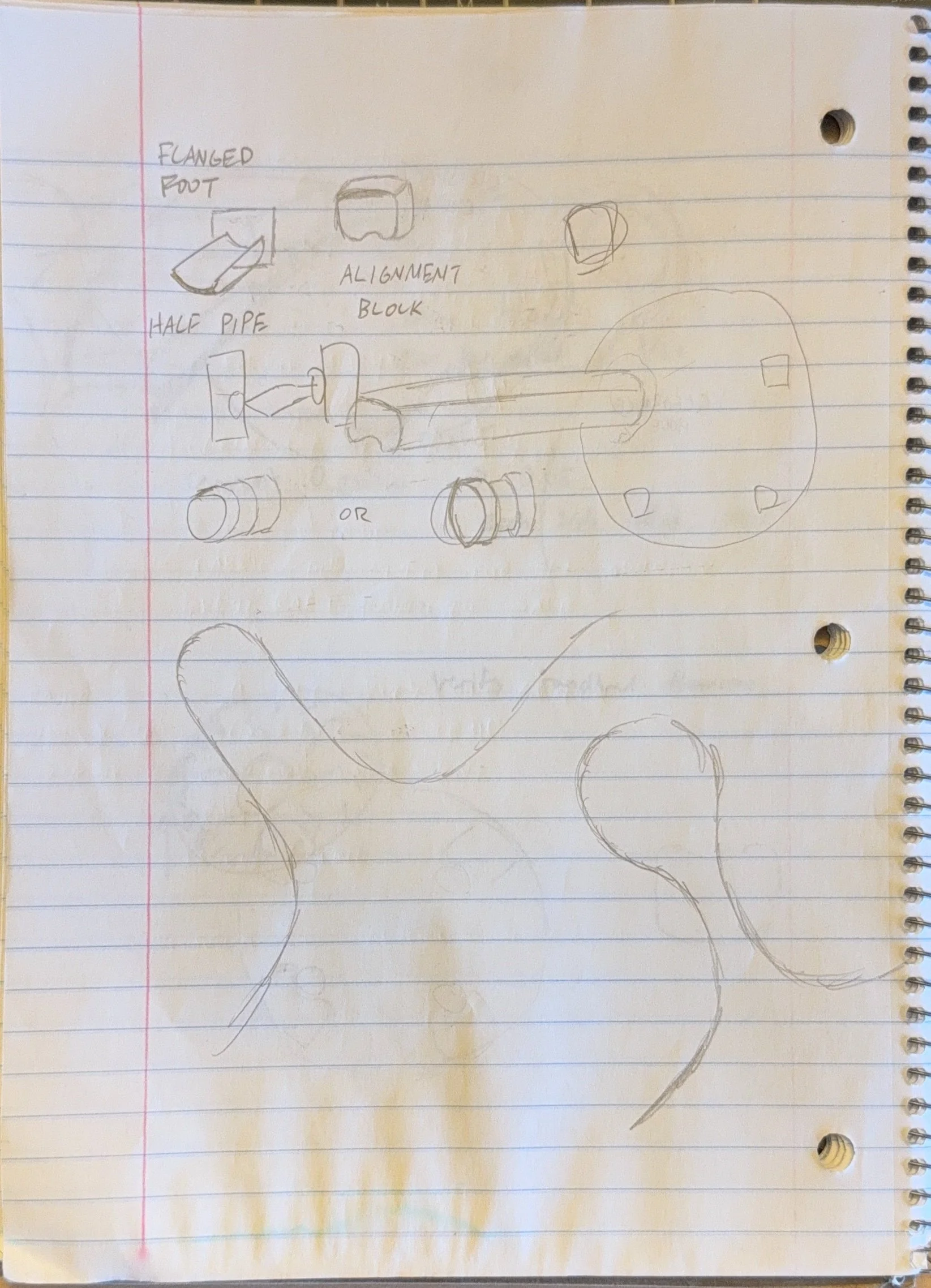
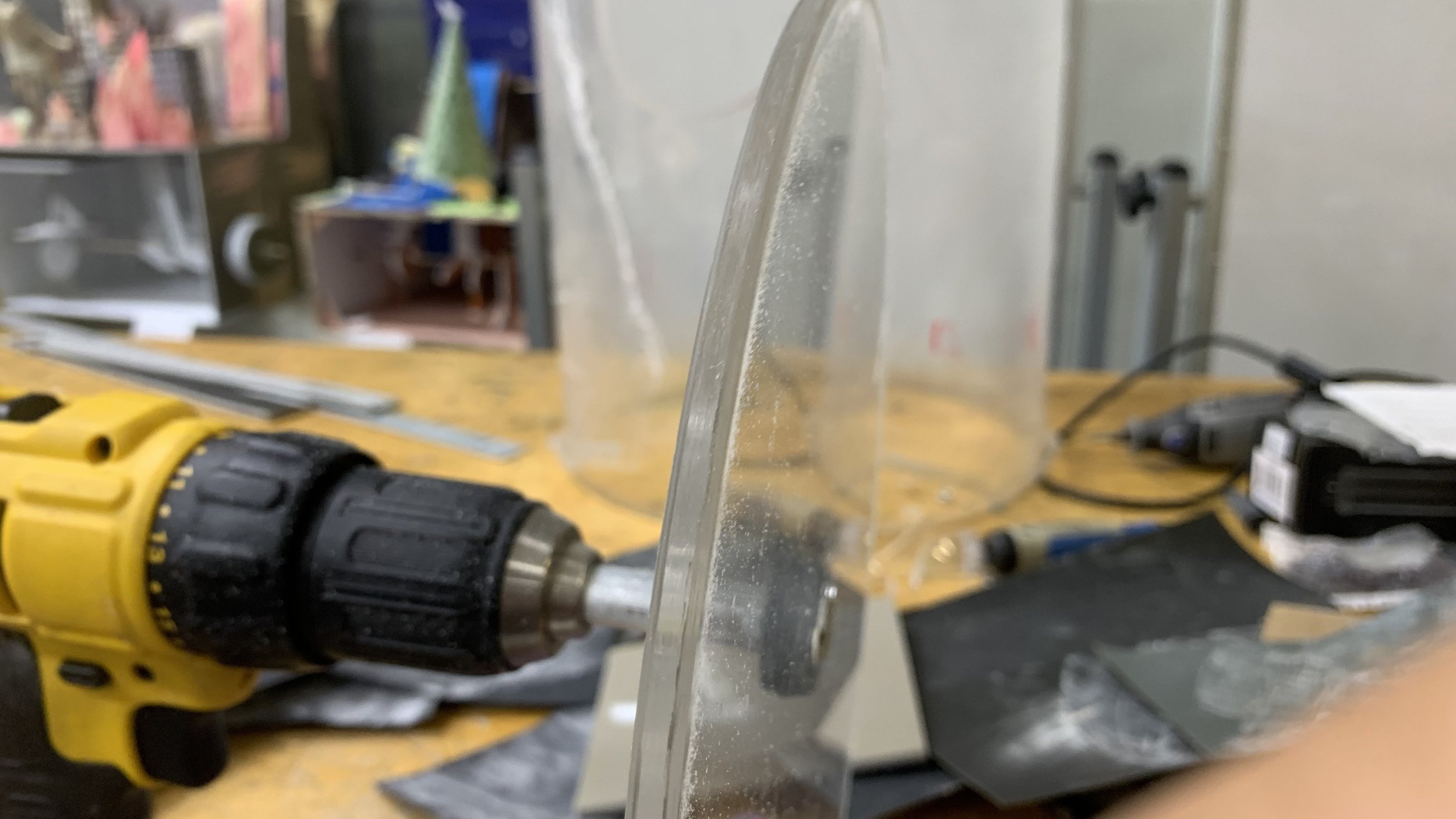
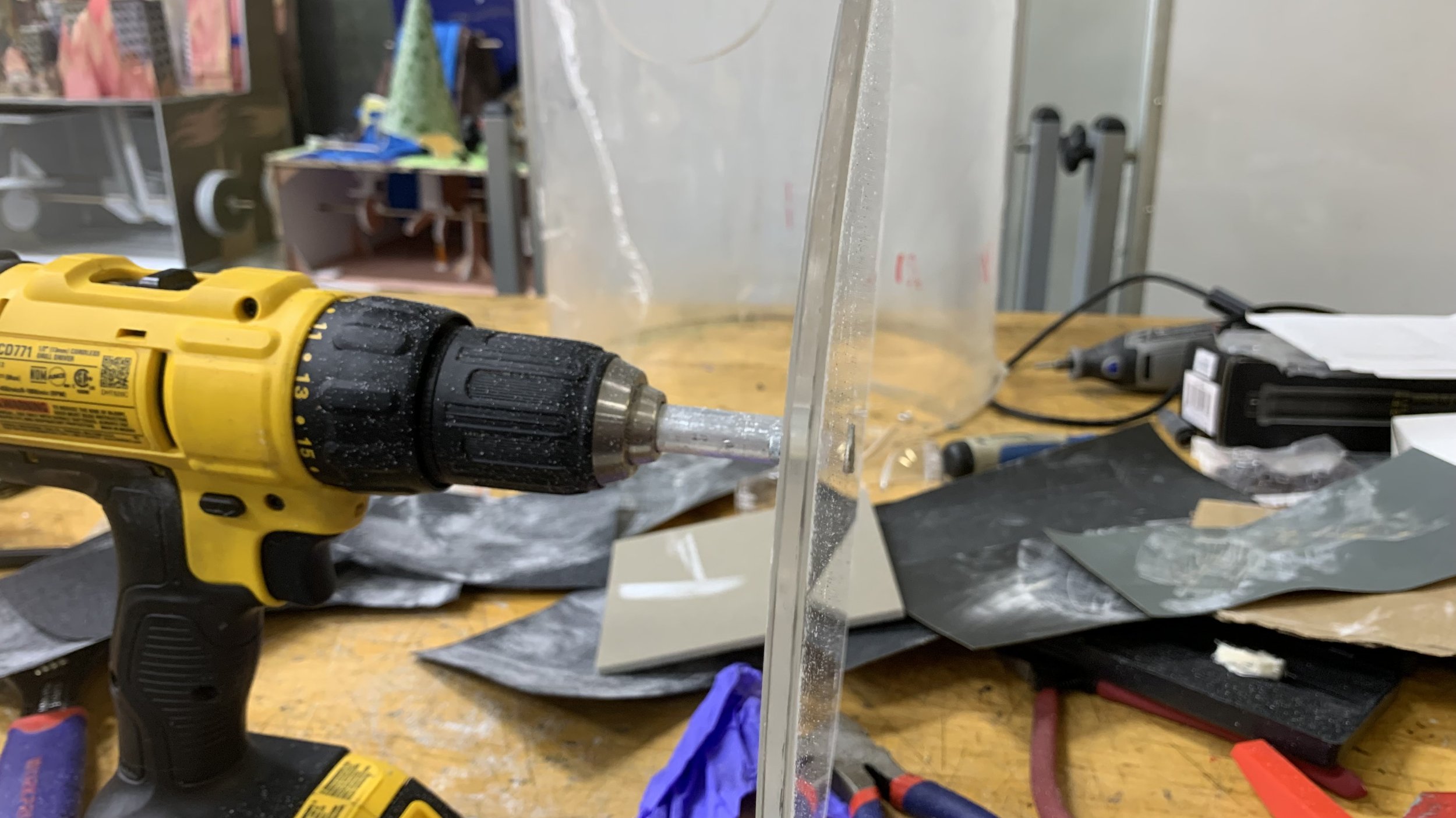
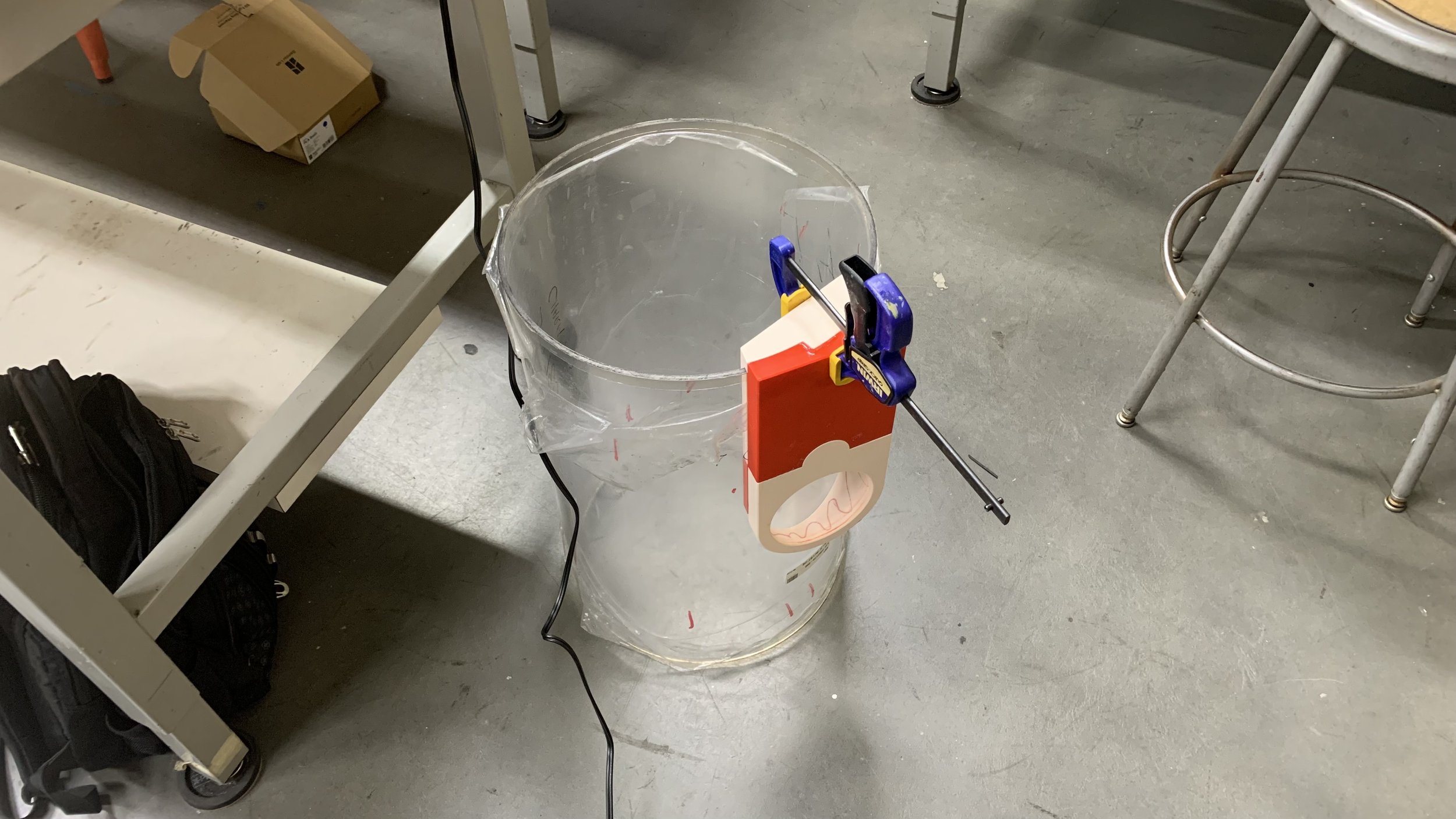
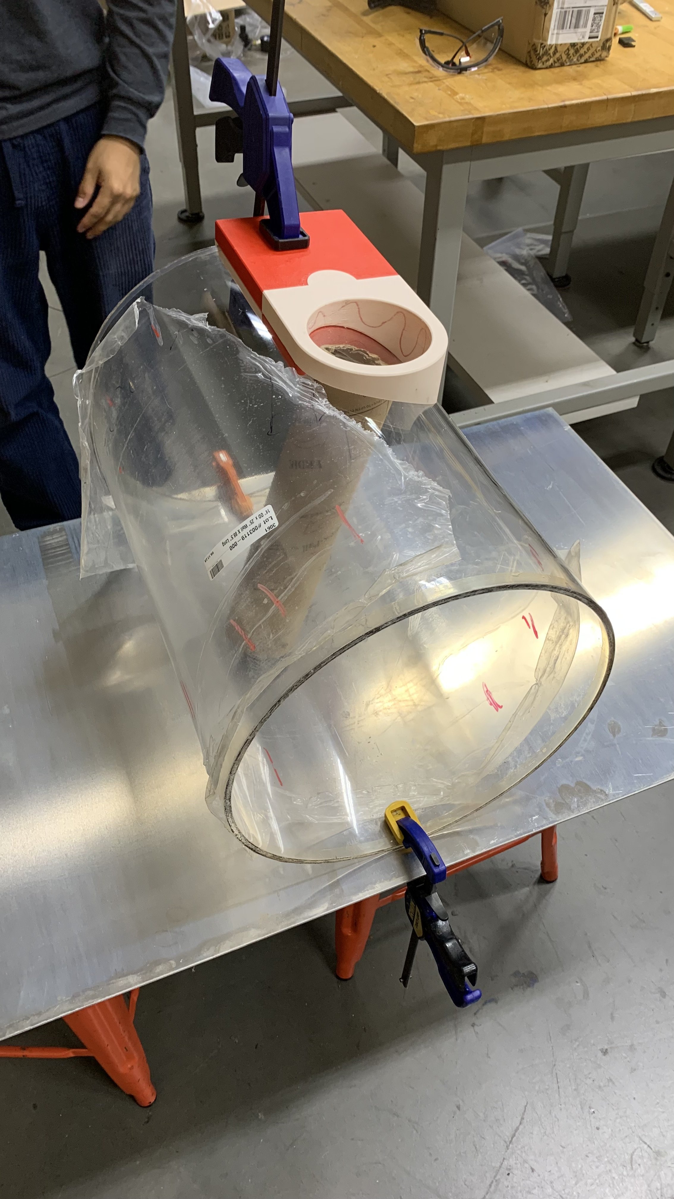
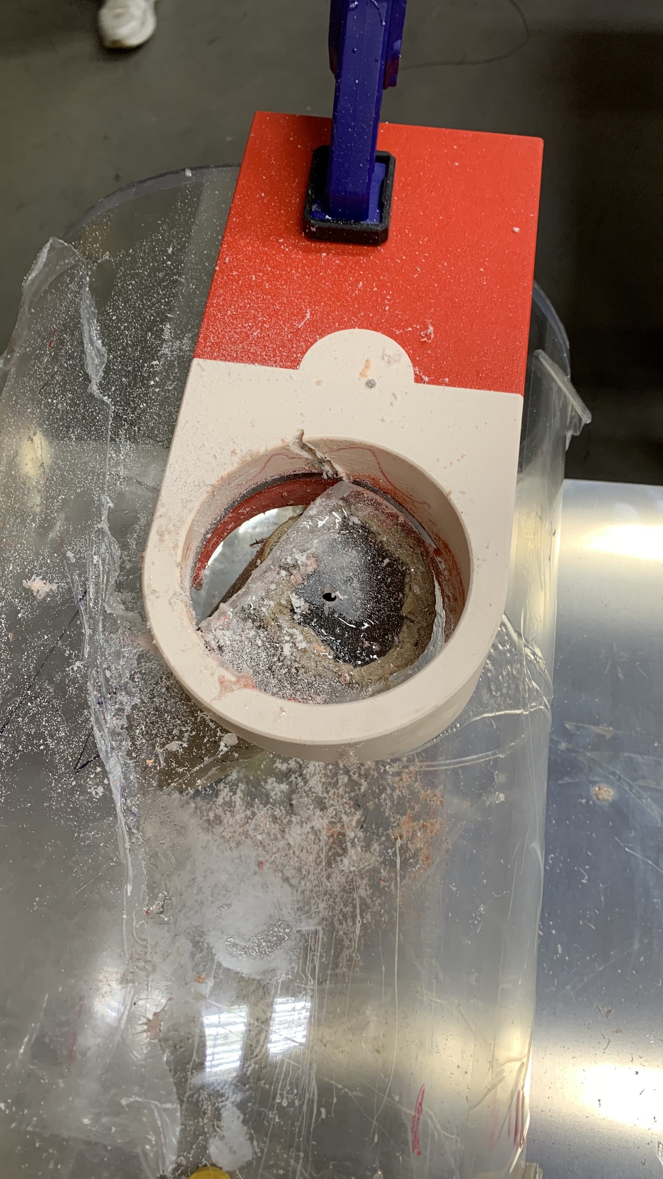
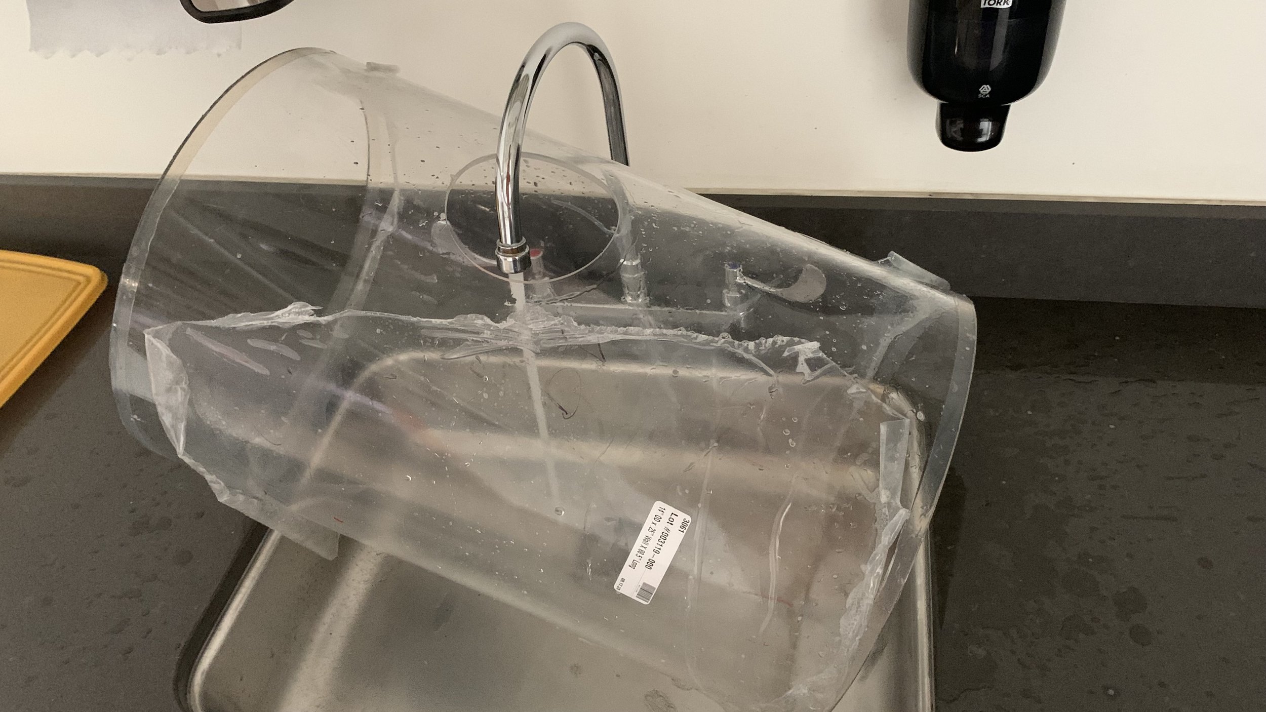
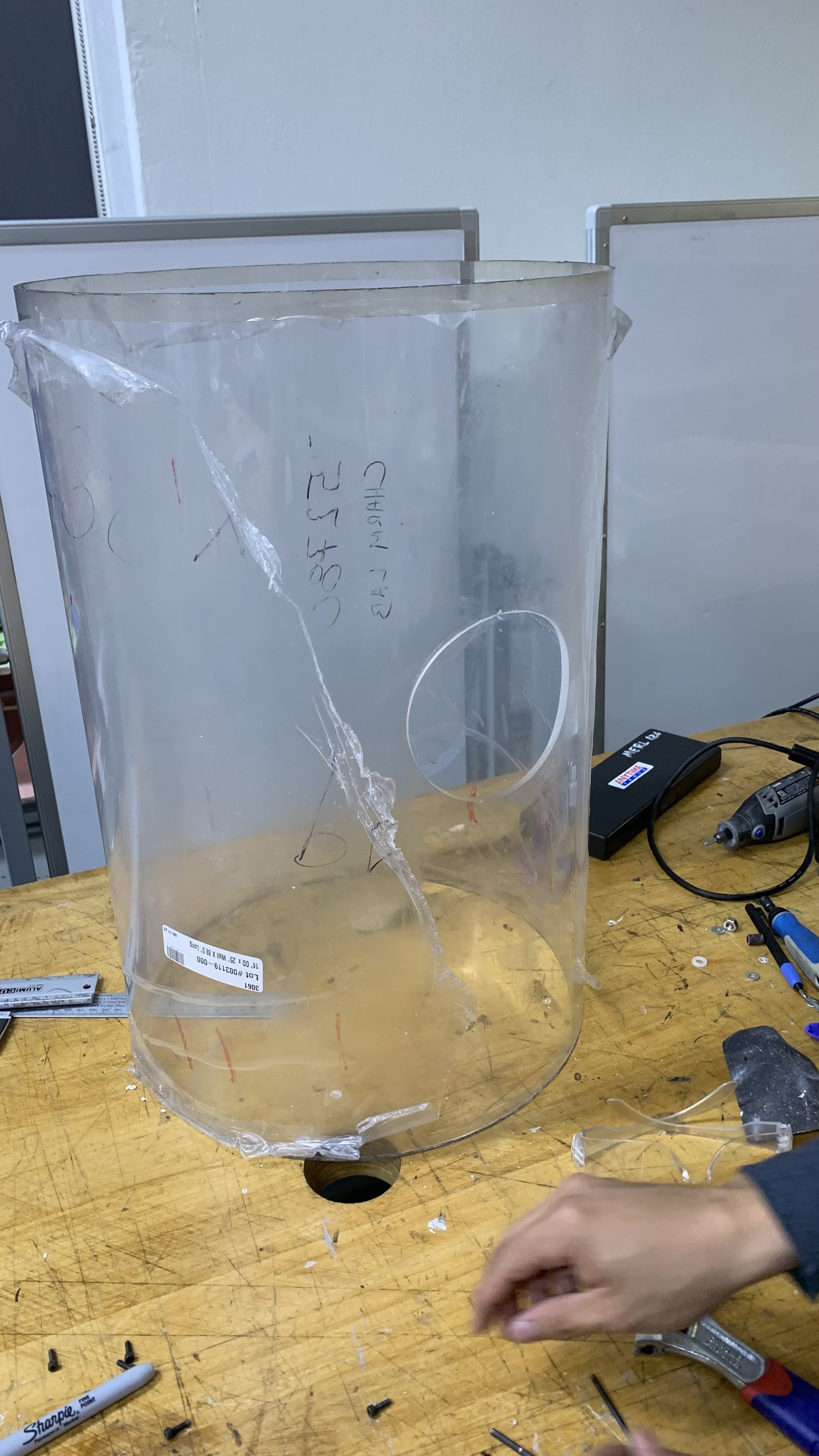
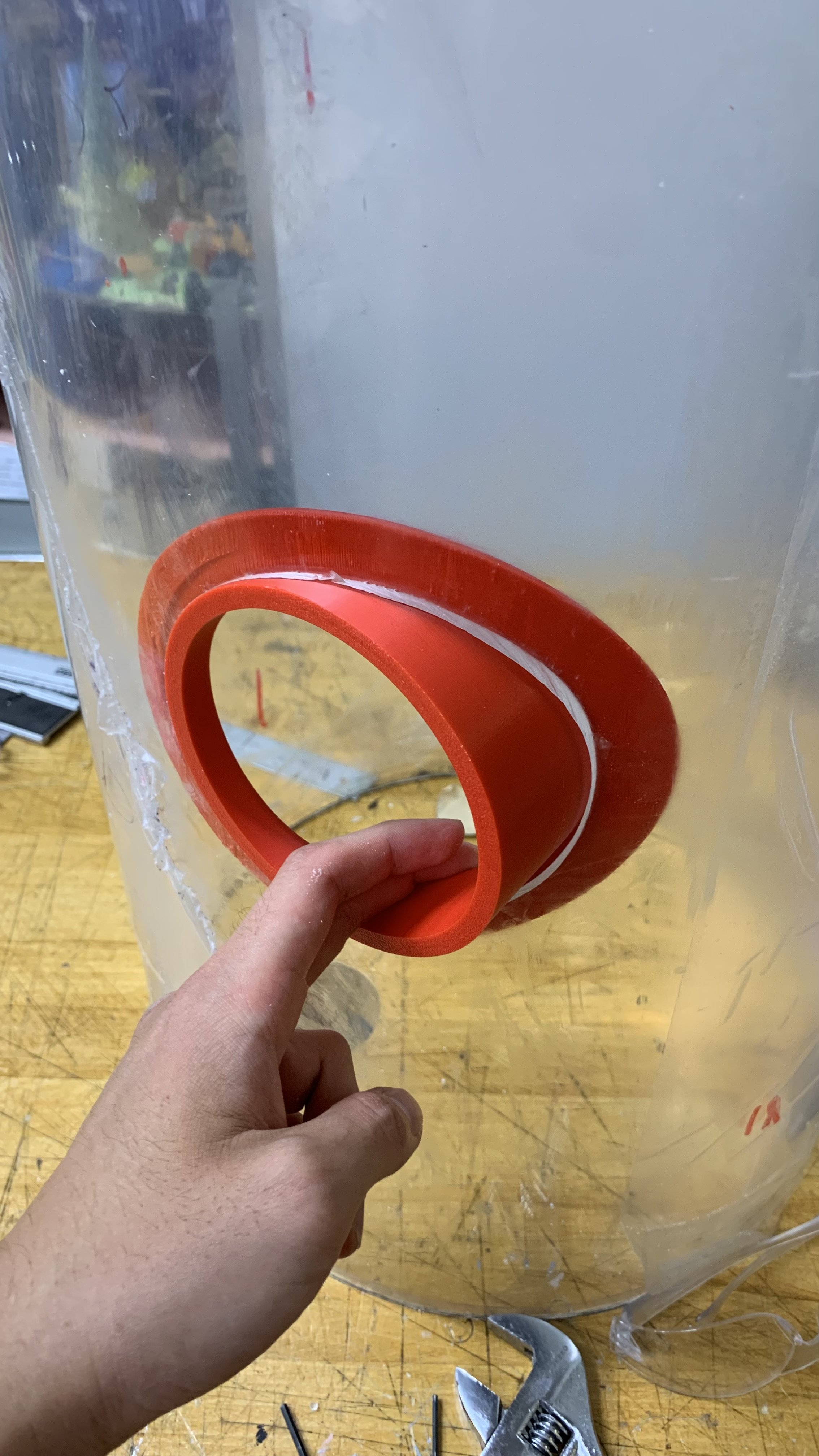
One crucial part to the base station was the hole where it exited the acrylic cylinder Not only was it a high pressure challenge to carve a hole out of a very expensive piece of acrylic, but the hole also had to be offset so it exited tangent to the spool’s diameter.
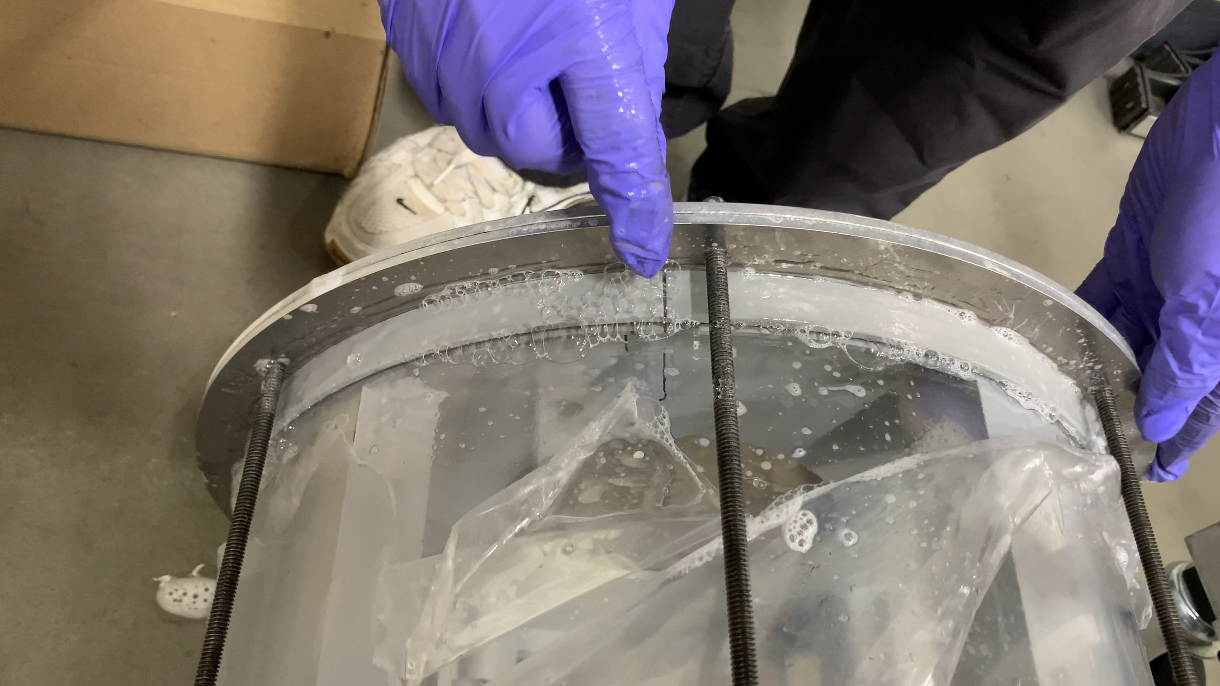
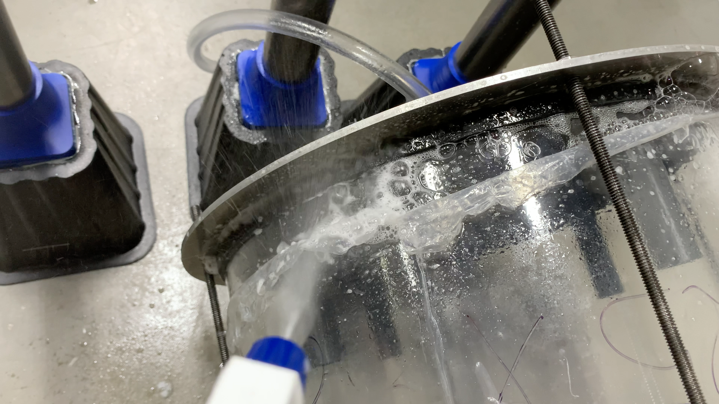
We developed a 3d printed jig that was pieced together in 4 parts. It slotted onto the acrylic cylinder and acted as a guide for the hole saw. Because the acrylic was hollow, we used a piece of cardboard tube to provide support. Due to the depth of the hole saw, pieces had to be dremeled away near the 2nd half of the operation. To prevent cracking and melting, dish soap was used as a lubricant and drilling was intermittent similar to pecking.
Handing off to testing
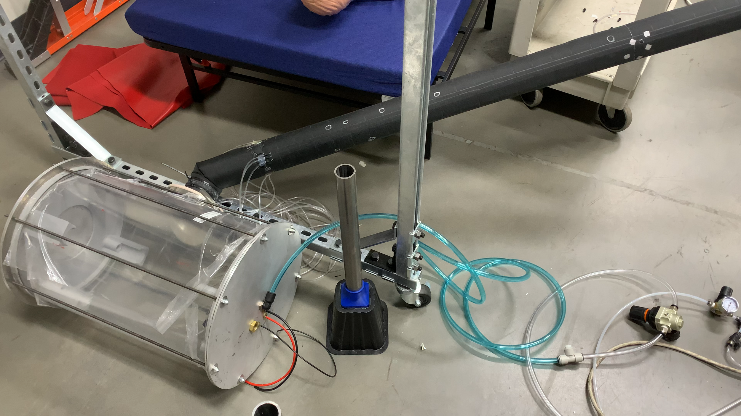
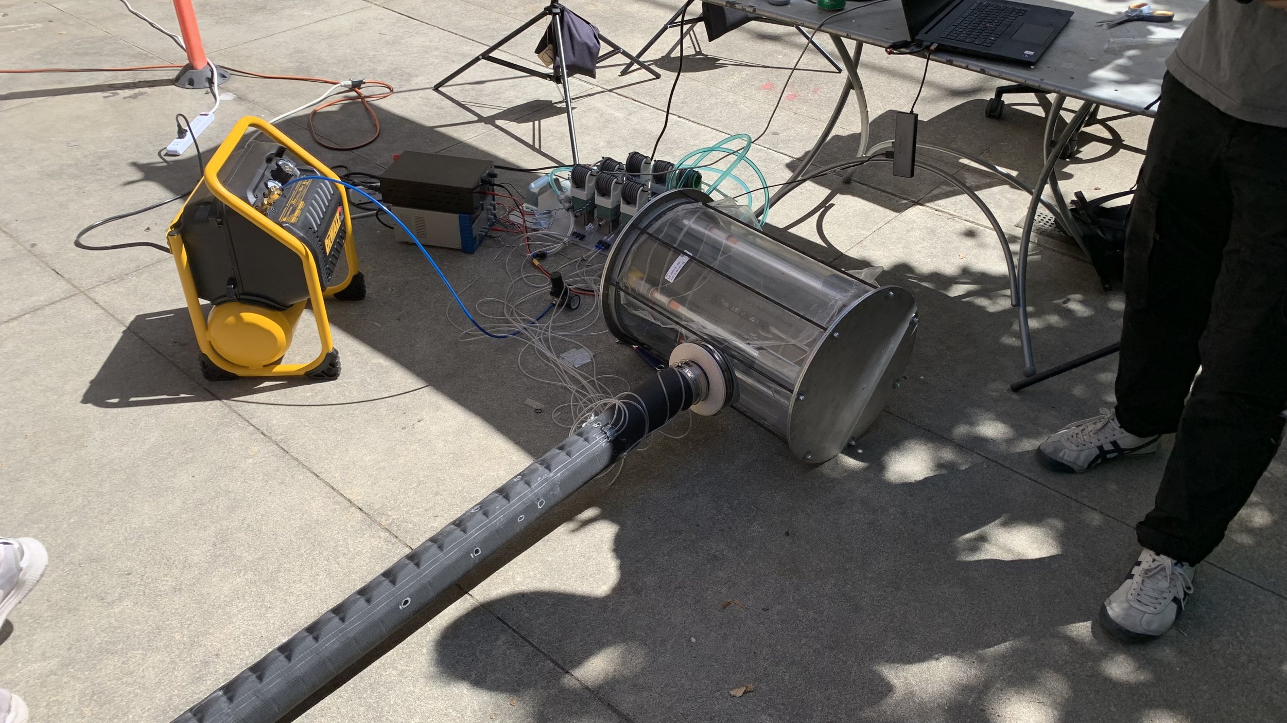
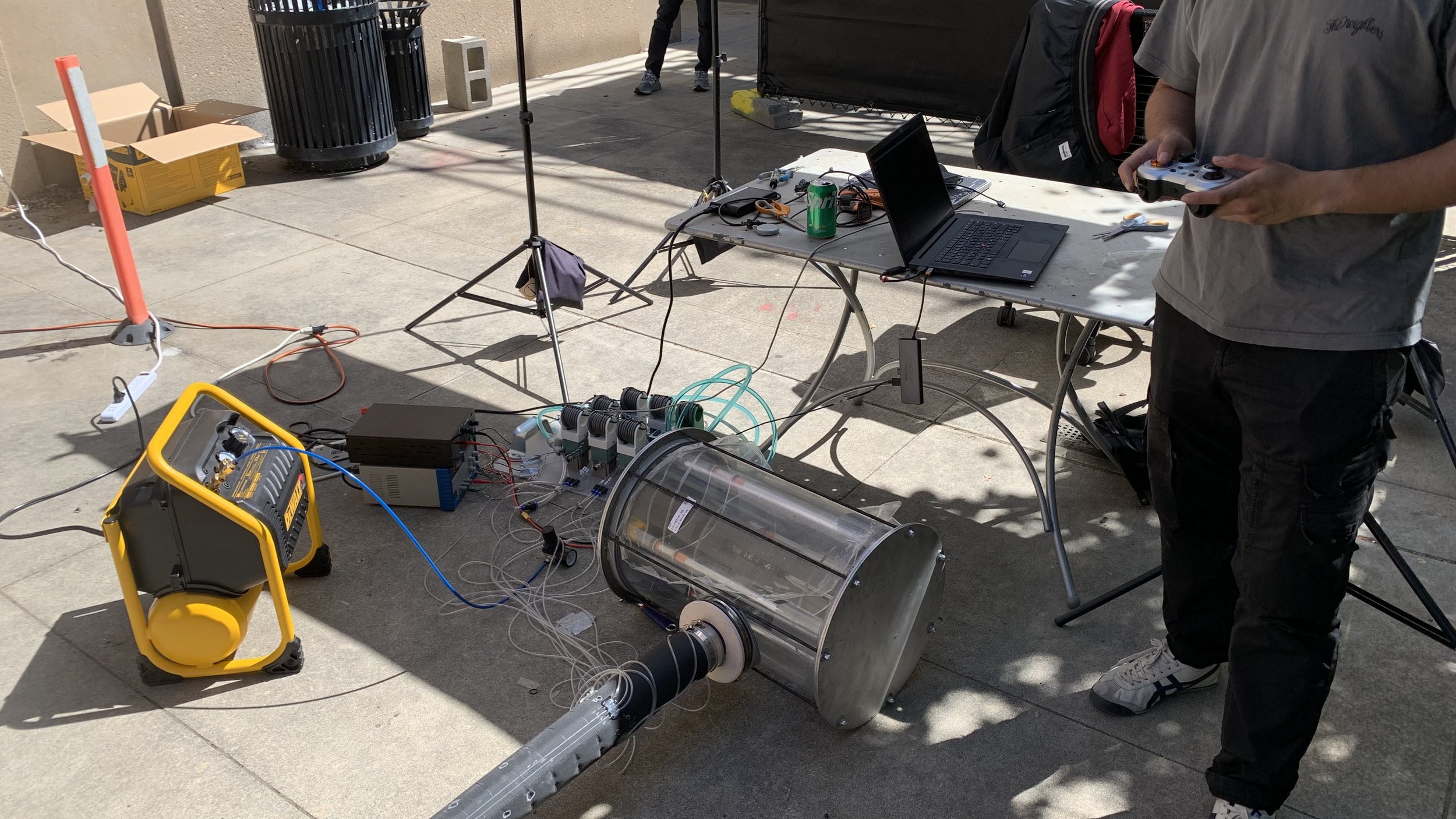
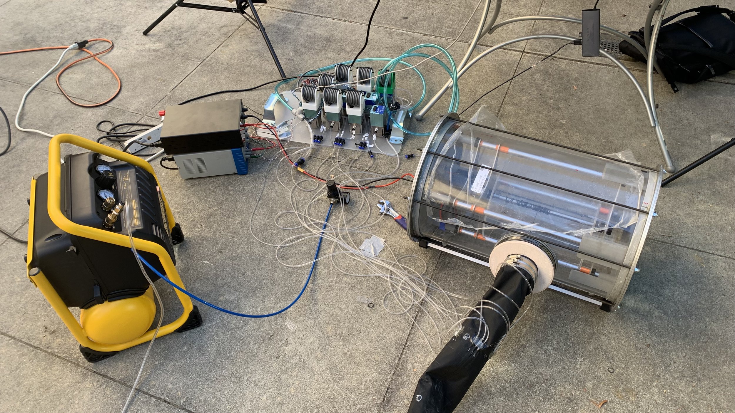
We performed a final pressure test with our assembly and the vine robot was able to inflate nominally. Once that was successful, we handed it off to our other teammates who are responsible for the electronics side of the robot.
A short clip here shows the “muscles” of the robot can be manipulated with a controller to navigate hard to reach areas
Future work
There are a lot of improvements that can be made, but the most important thing was that we were able to deliver a baseline product that could demonstrate the robot’s function nominally.
The next iteration will be drastically smaller volumetrically, have an easier method for taking out the carriage system, and a better method for sealing. The current base station was a leak galore. It was extremely frustrating to have to constantly patch it in order to keep the pressure in. Once the leaks were resolved, they would reappear after transporting it through rough terrain. Our next iteration will tackle this aggravating problem.
Gratitude
I would like to thank the members of my team:
William — for recruiting me to this project and had many technical discussions for making design decisions
Yimeng — for being a great mentor, supportive of our work, and a source of uplifting team dynamics
Sal — an incredible teammate who puts selfless amount of time and dedication into making the product real.

