Make something that makes something
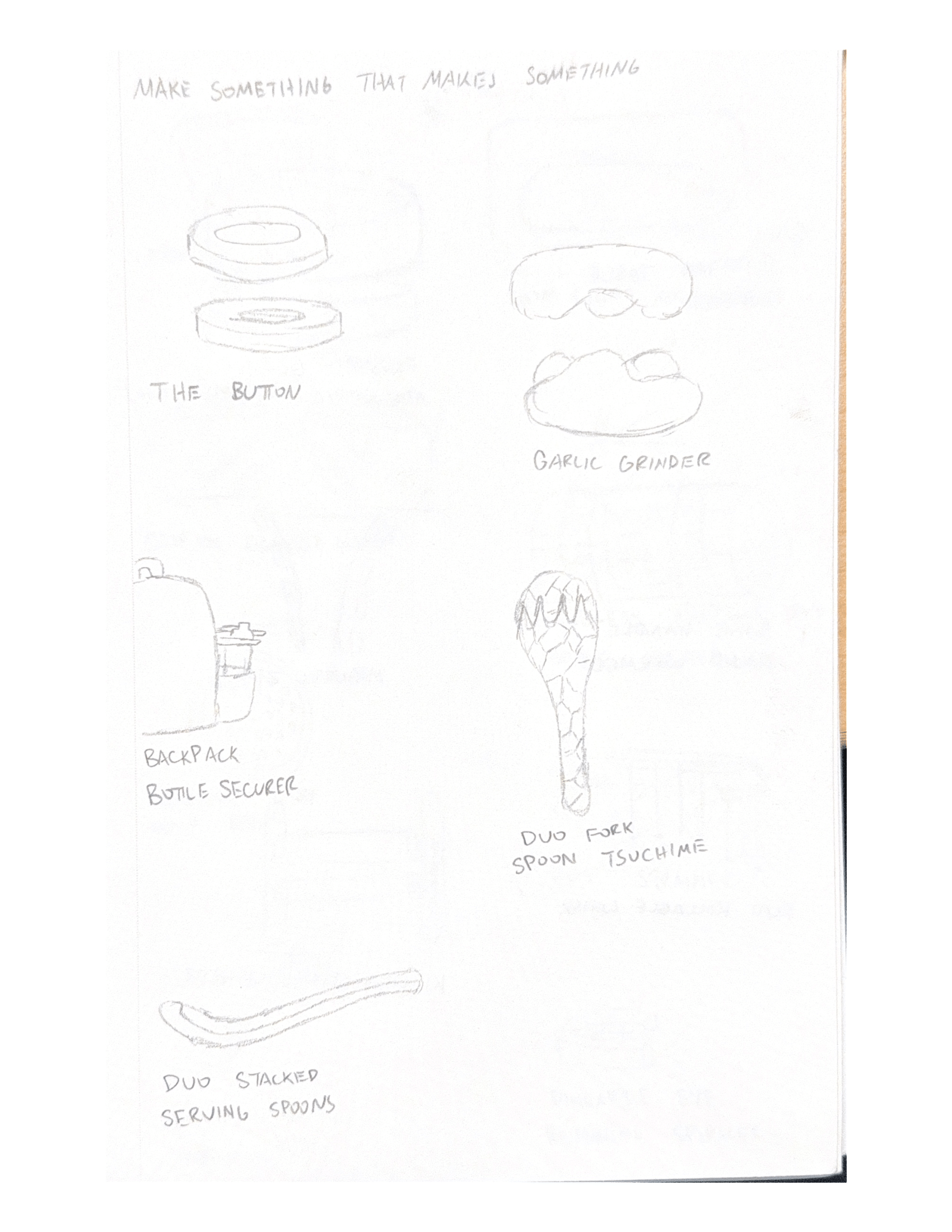
Was the prompt for our final project in CNC. I wanted a more abstract take on the prompt instead of making something concrete like a cookie cutter, dough shaper or letter press. I decided to make a room light up.
2024
Inspiration
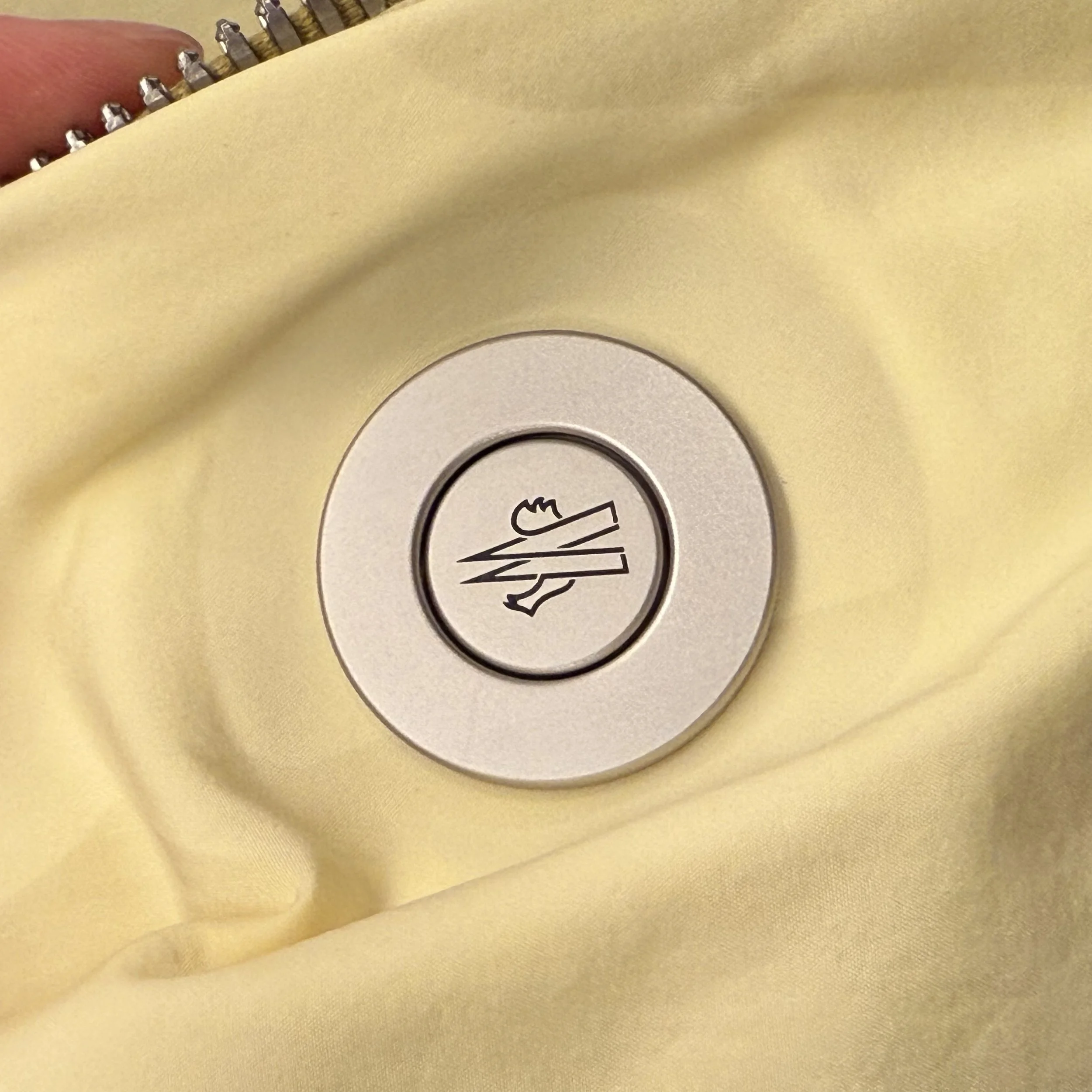
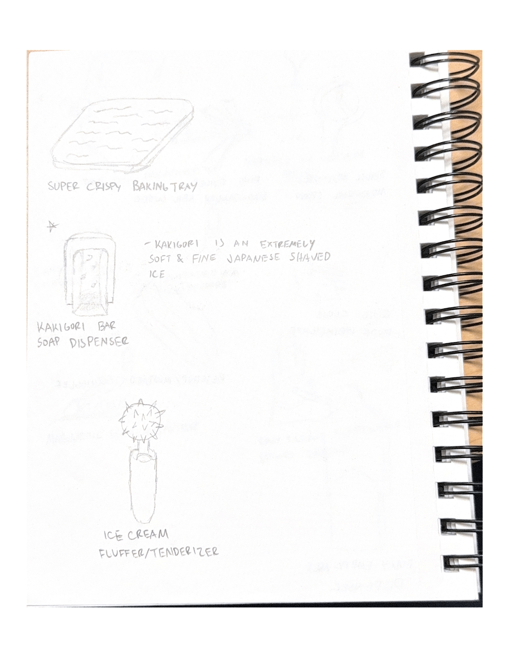
I read all about the button the past few months from a collaboration between LoveFrom and Moncler. I was adamant about recreating and make a button that makes a satisfying click. However, I was quickly shot down as it was deemed an engineering problem rather than a design problem.
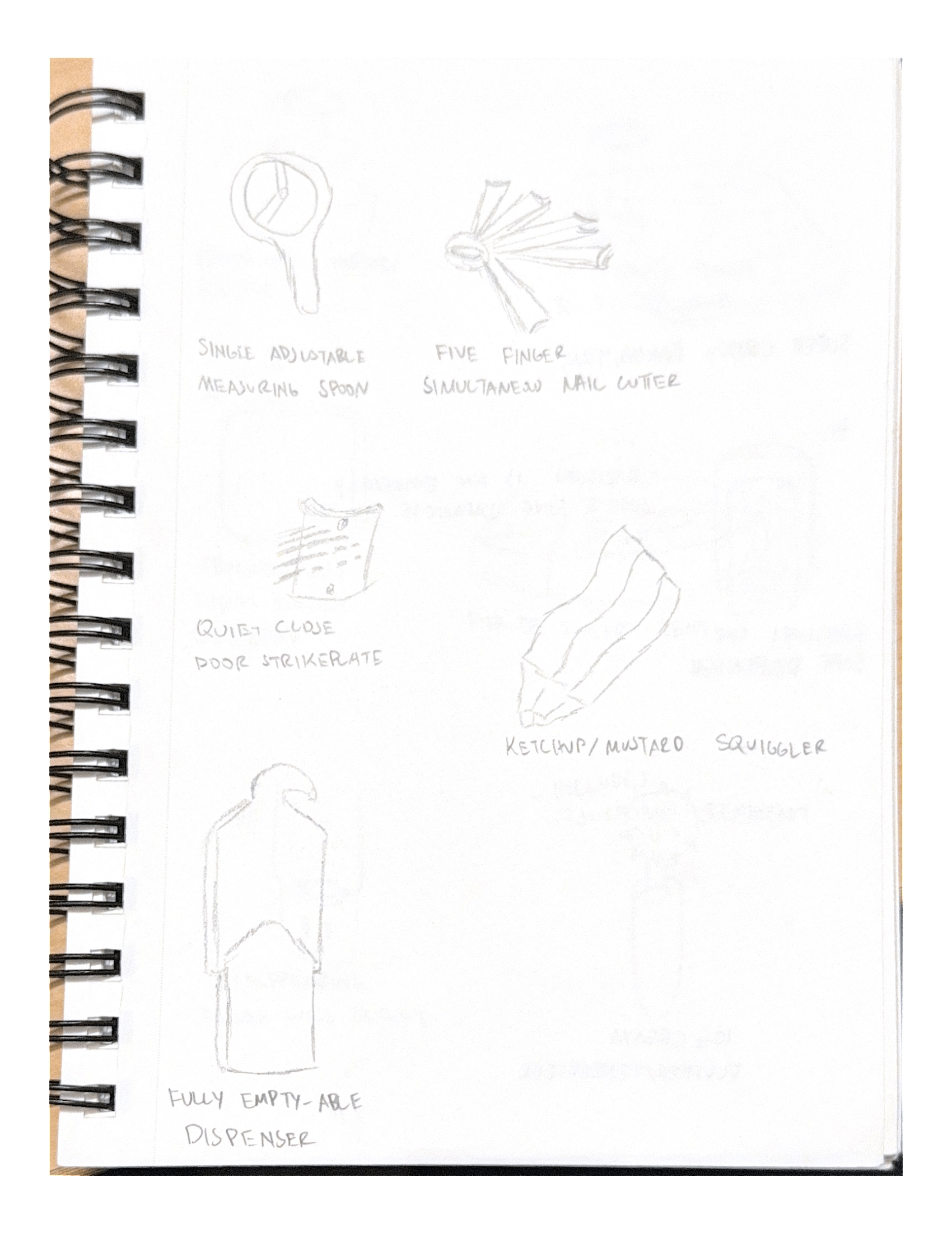
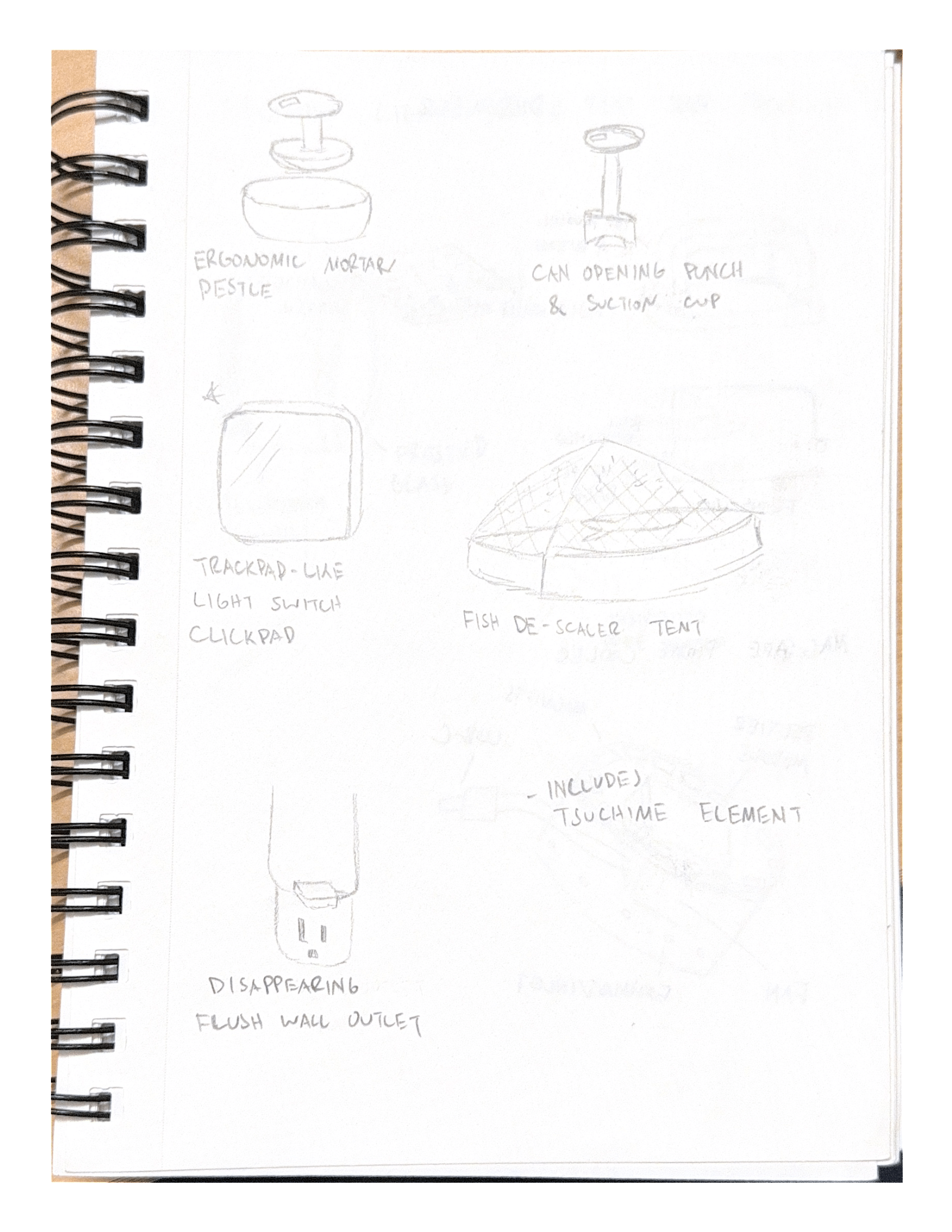
Ultimately, I moved onto redefining a residential staple: the light switch. It’s in every room, everyone is familiar with how it works, and it’s boring. I wanted to redesign it and give it a modern twist.
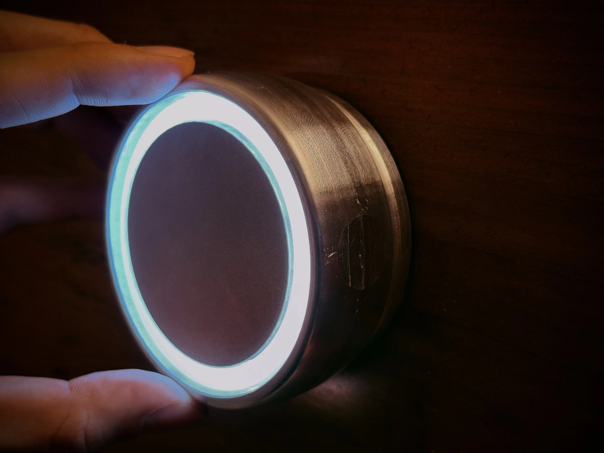
It will have a glowing ring that is on when the lights are off and off when the lights are on; it acts as a night light, location indicator, as well as for aesthetics. The entirety is a button. The ring would rotate to adjust brightness for rooms with dimmers, but was not included for the sake of scoping this project.

CAD
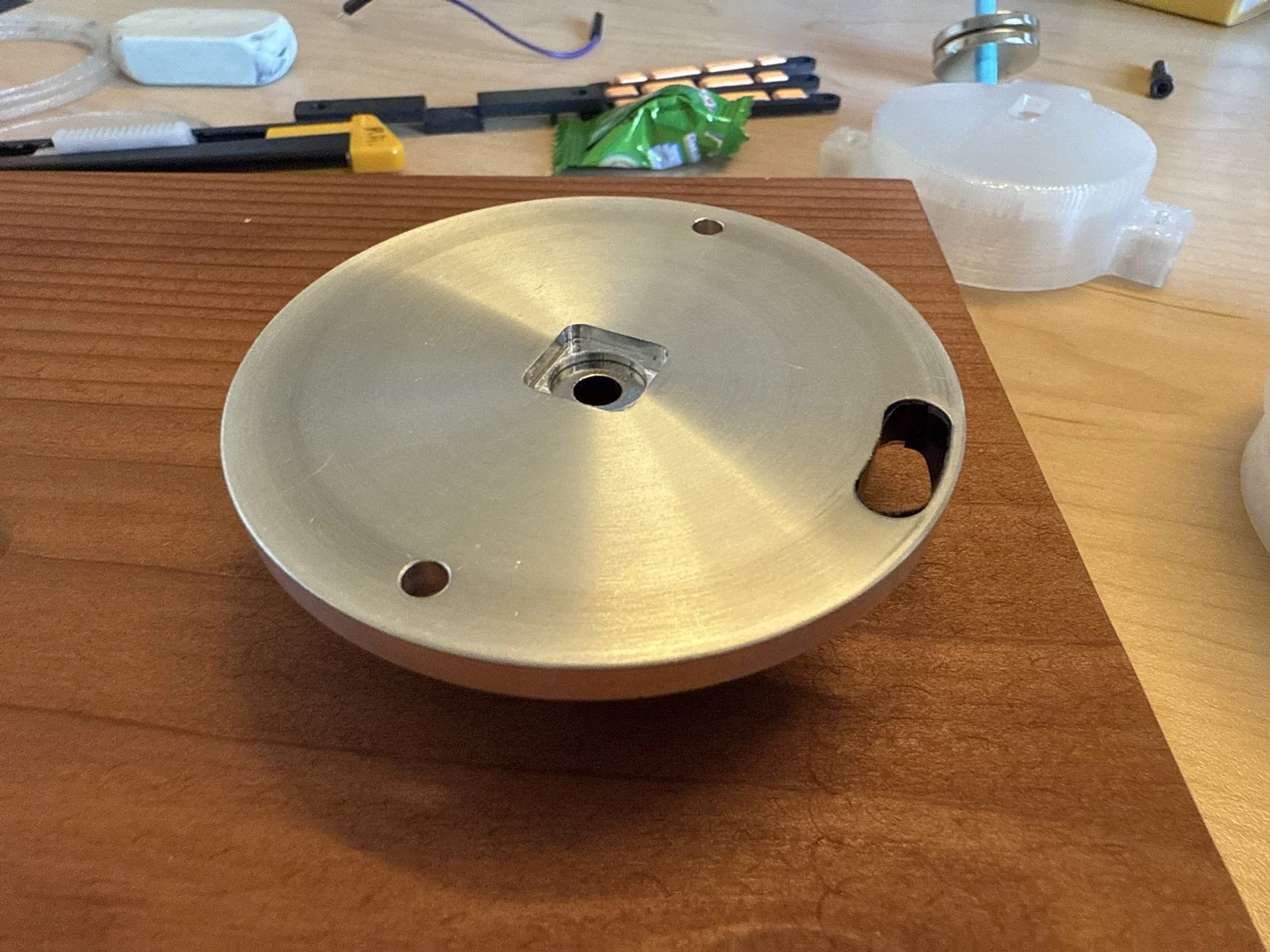
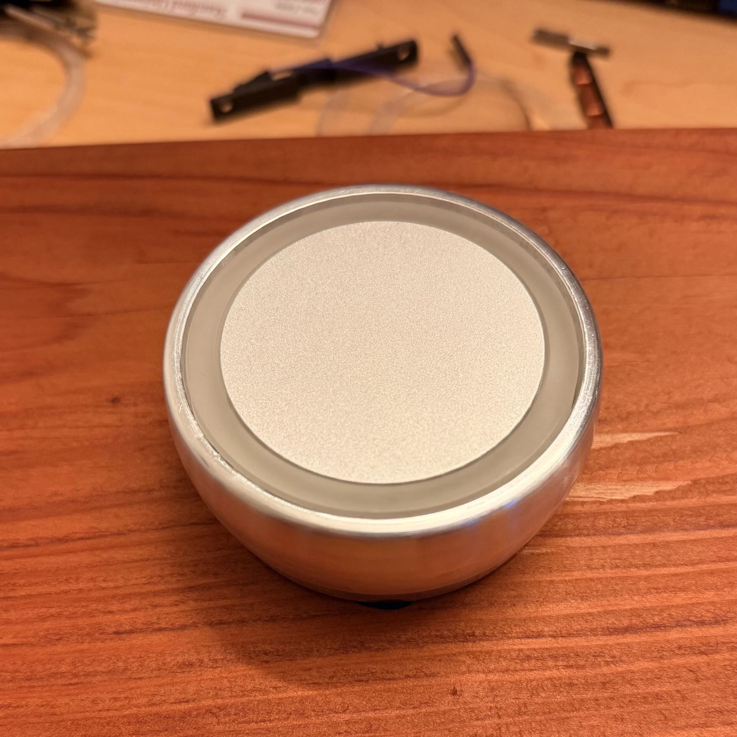
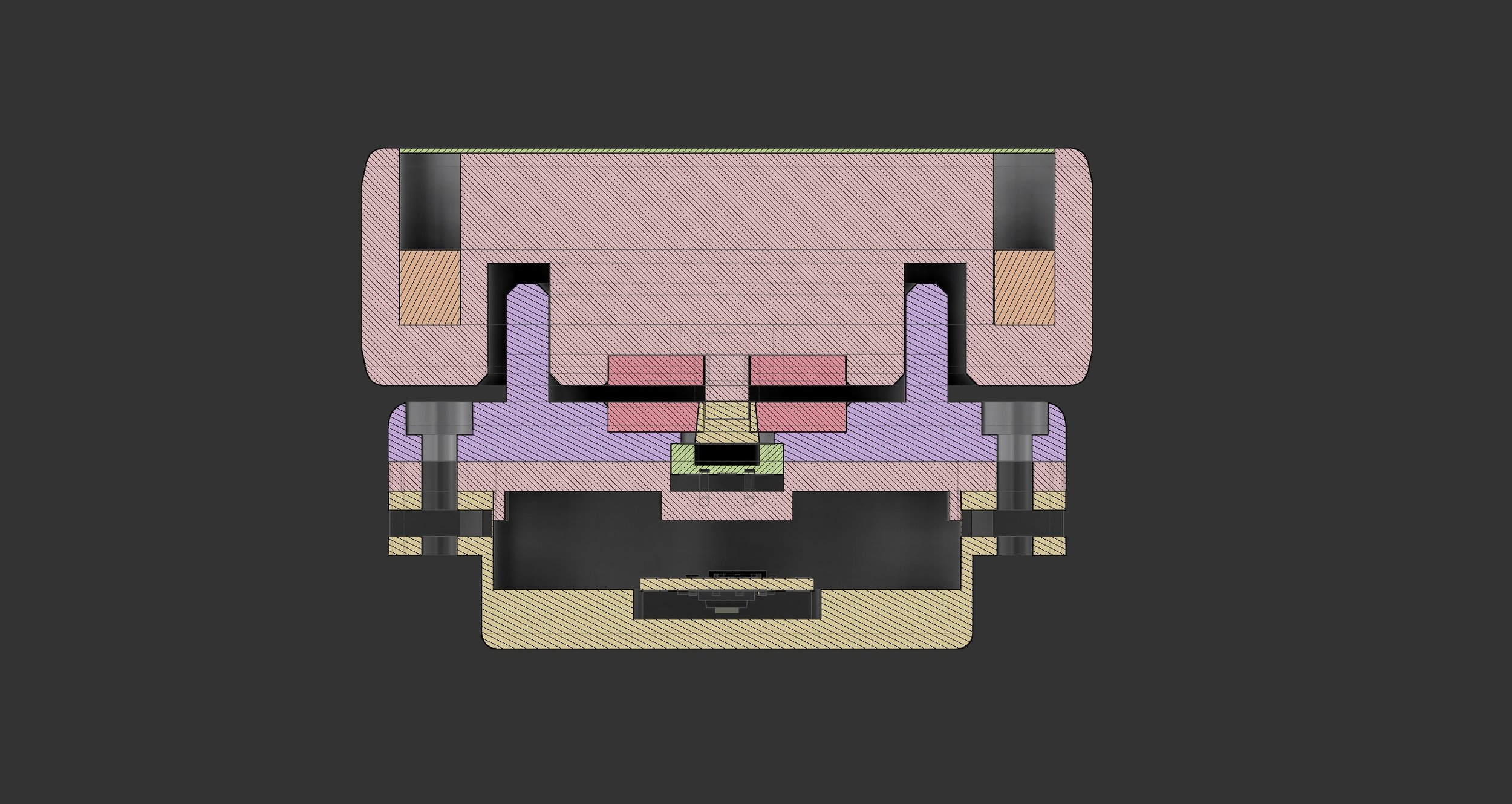
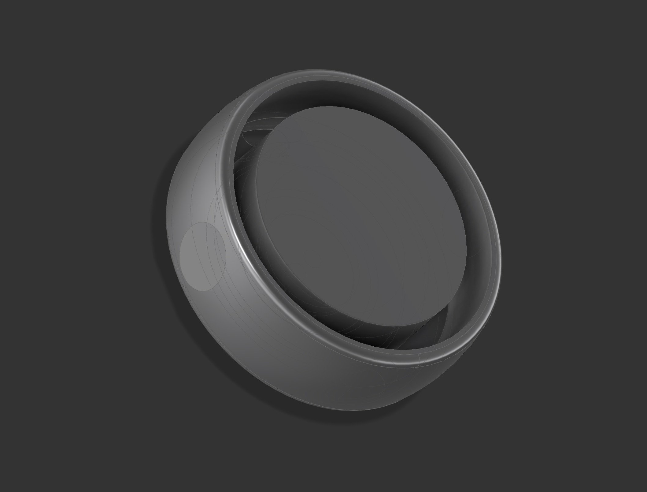
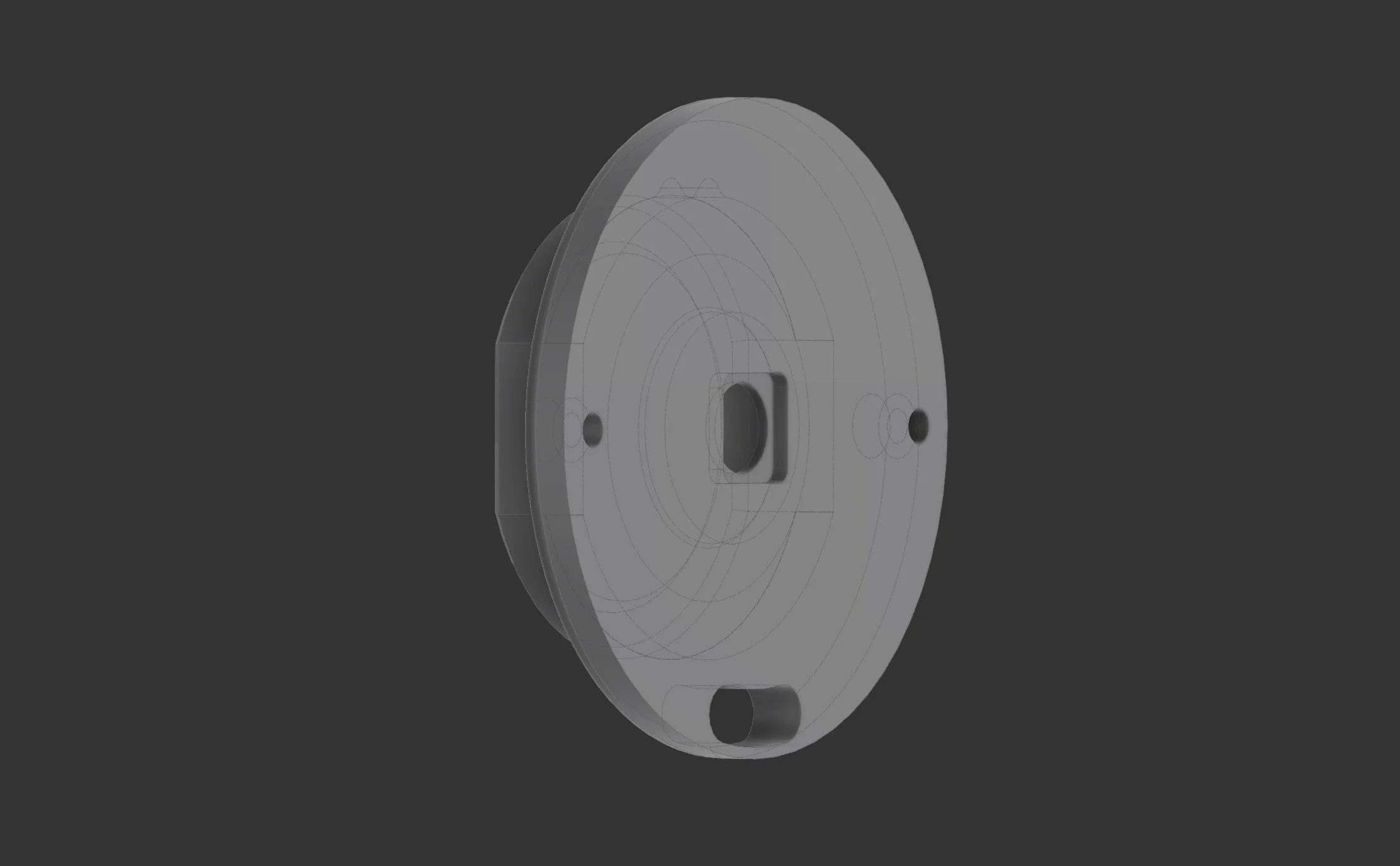
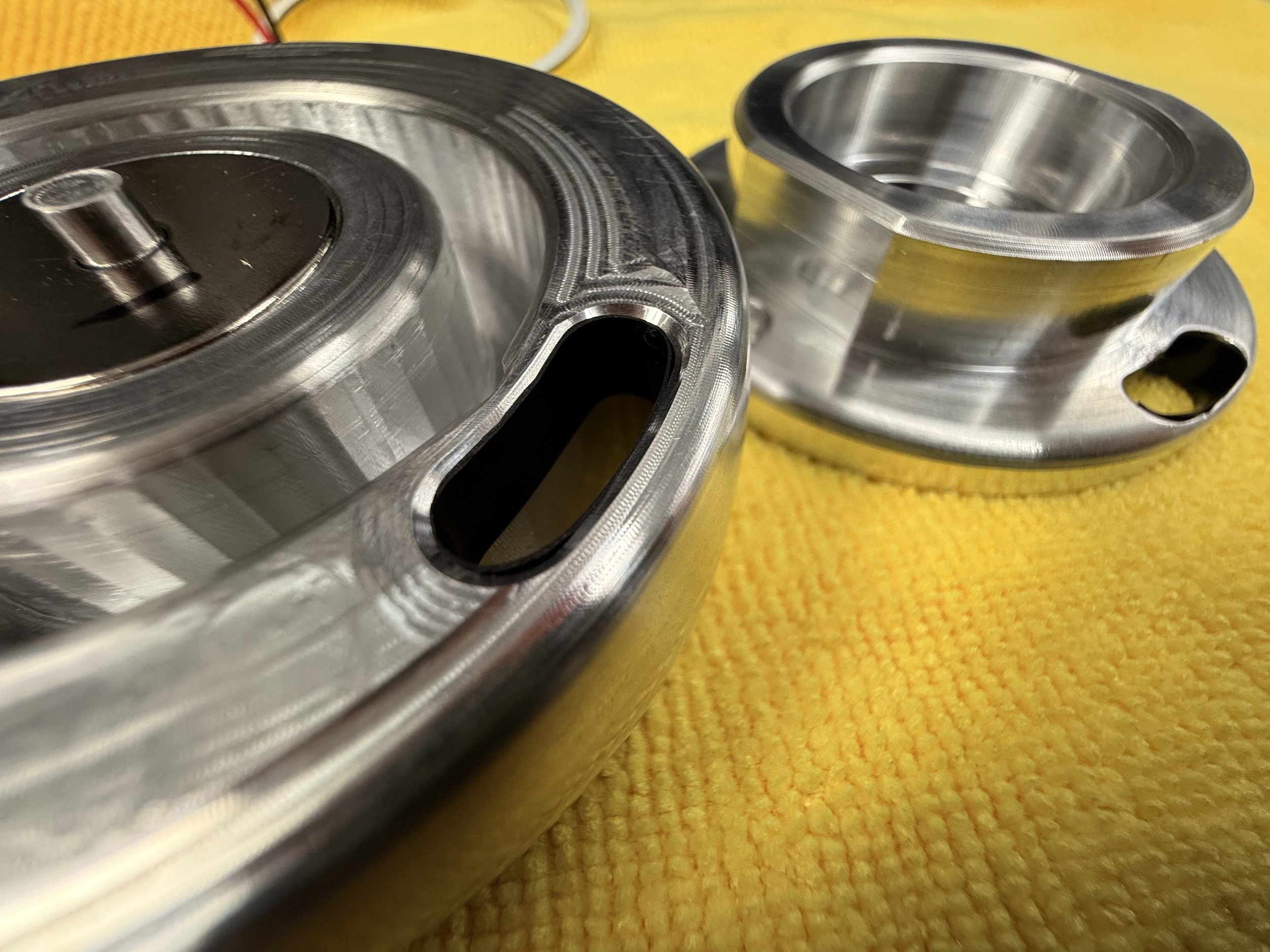
This is the button. There is the main body that the user interacts with on top. Underneath is a wall plate that attaches the body to the wall, and underneath is a housing for the electronics. The ring slot in the main body allows for a ring LED, color filter, and diffusers to sit in. It will be covered at the top by a frosted glass sheet, which is glued to the center and sits flush with the top edge.
The wall plate has 2 counterbore mounting screws to attach the electronic housing as well as the wall.


First interaction with glass
I really wanted a glass cover for my button. I wanted it to be frosted so it would diffuse the ring light as well as feel soft and supple if the user touches it. It would also contrast the light machined finish shine of the aluminum on the edge.
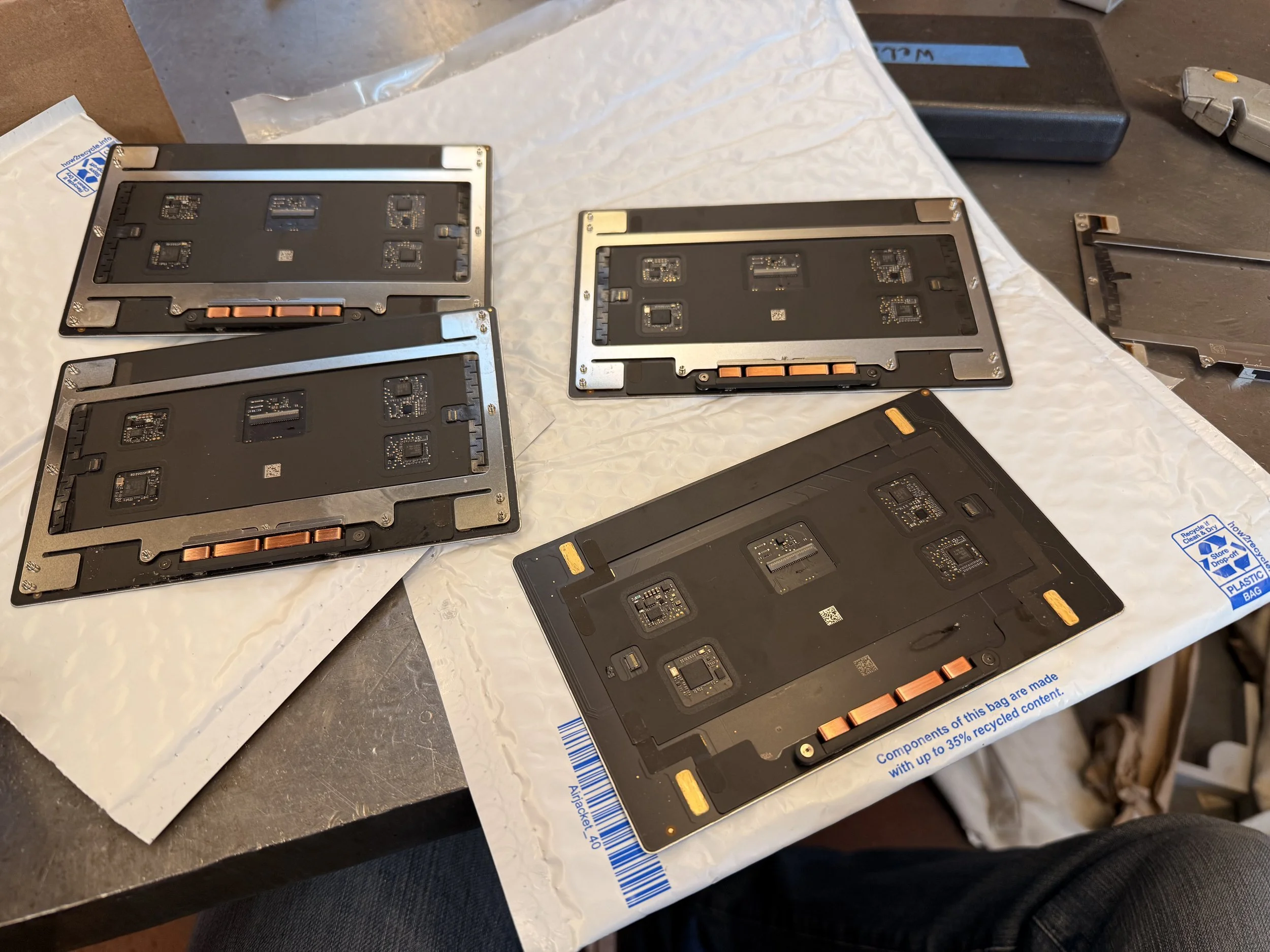
I decided to get some MacBook trackpad parts online as they were already chemically etched to have an incredibly smooth frosted finish.
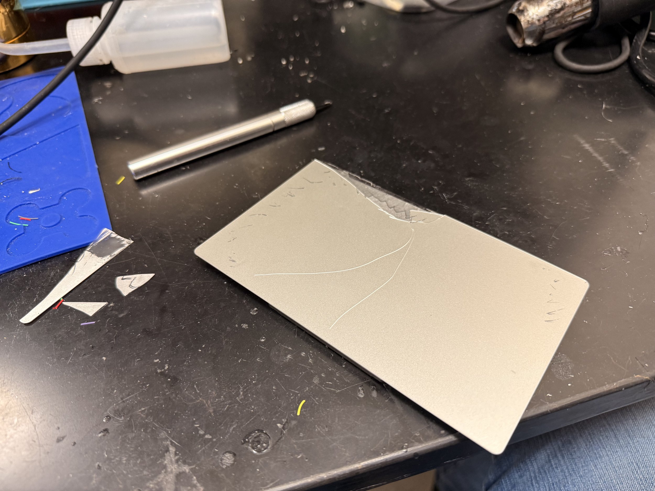
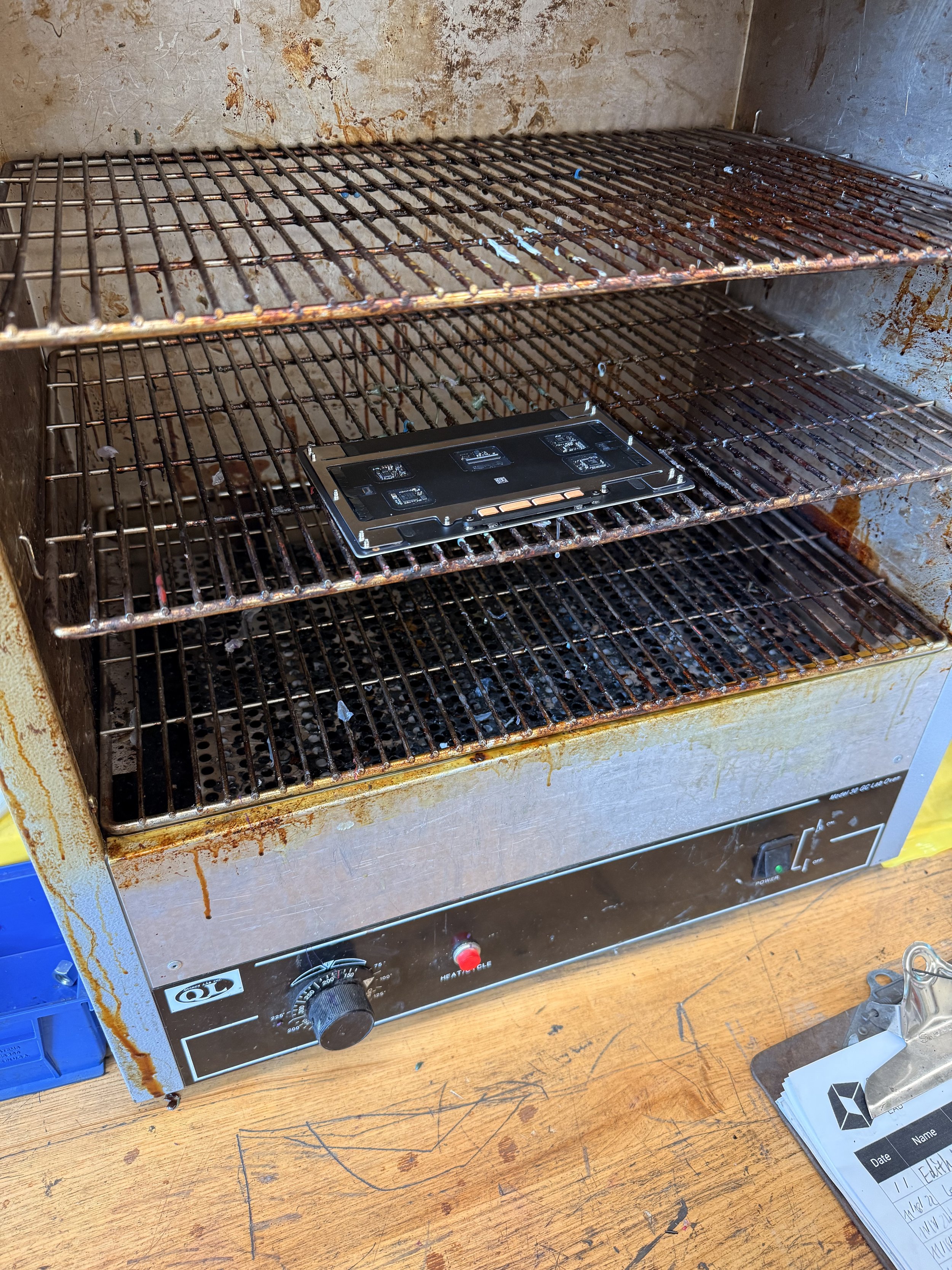
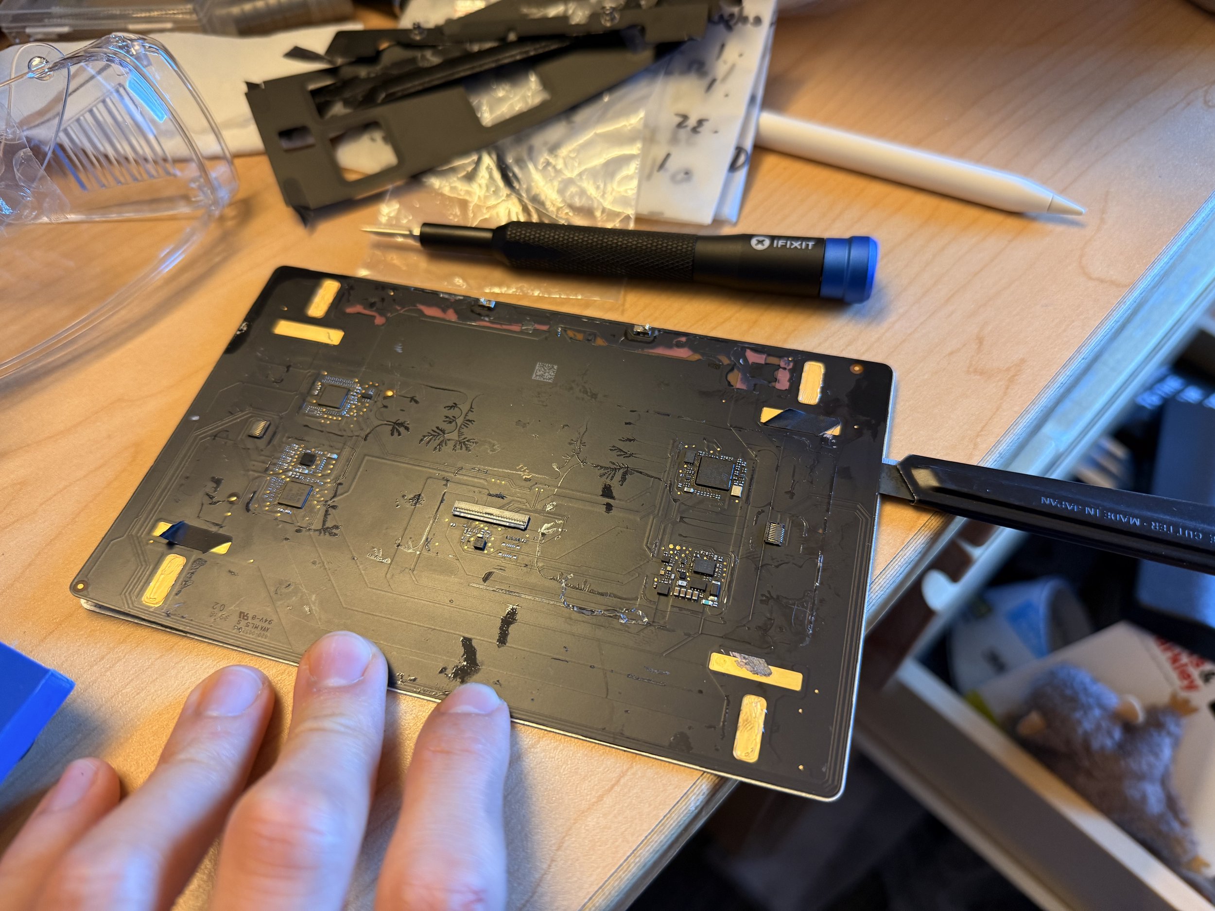
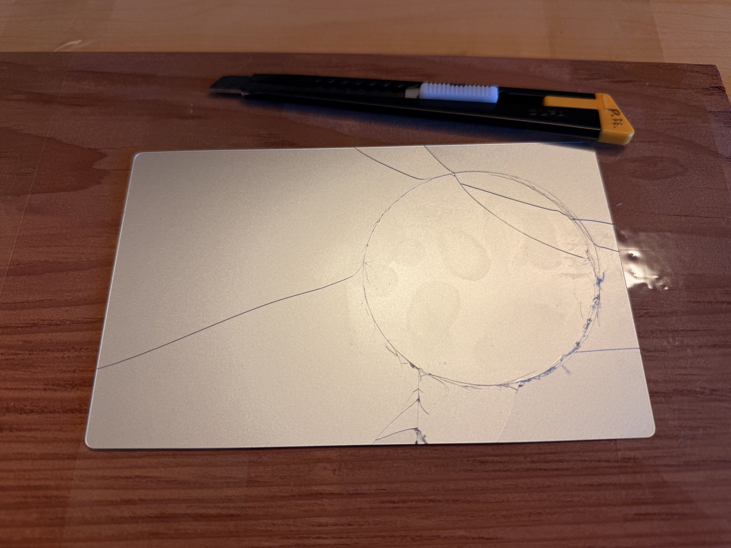
My first thought was to pry away the electronics from the back with an X-Acto knife and saw off the unreachable part with fishing line. Unfortunately, too much bend and the glass decided to crack. It was really hard to work with as it was only 0.55mm thick. I also tried heating it on the wax oven, but it was hot enough to melt the adhesive.
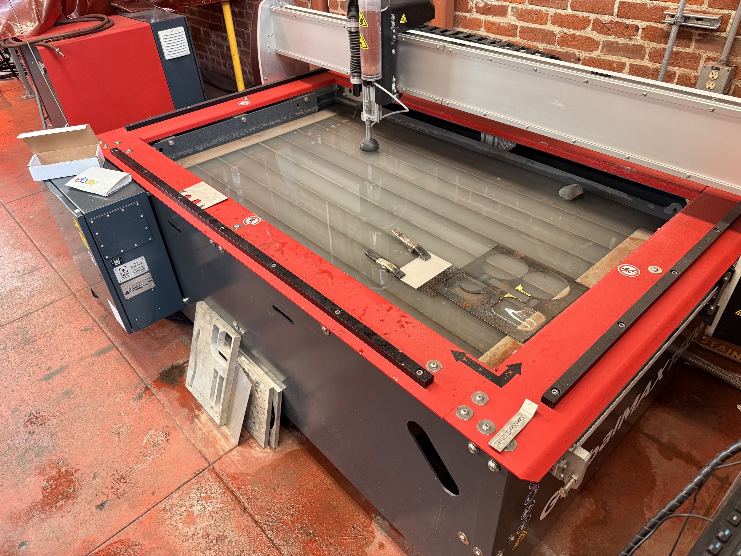
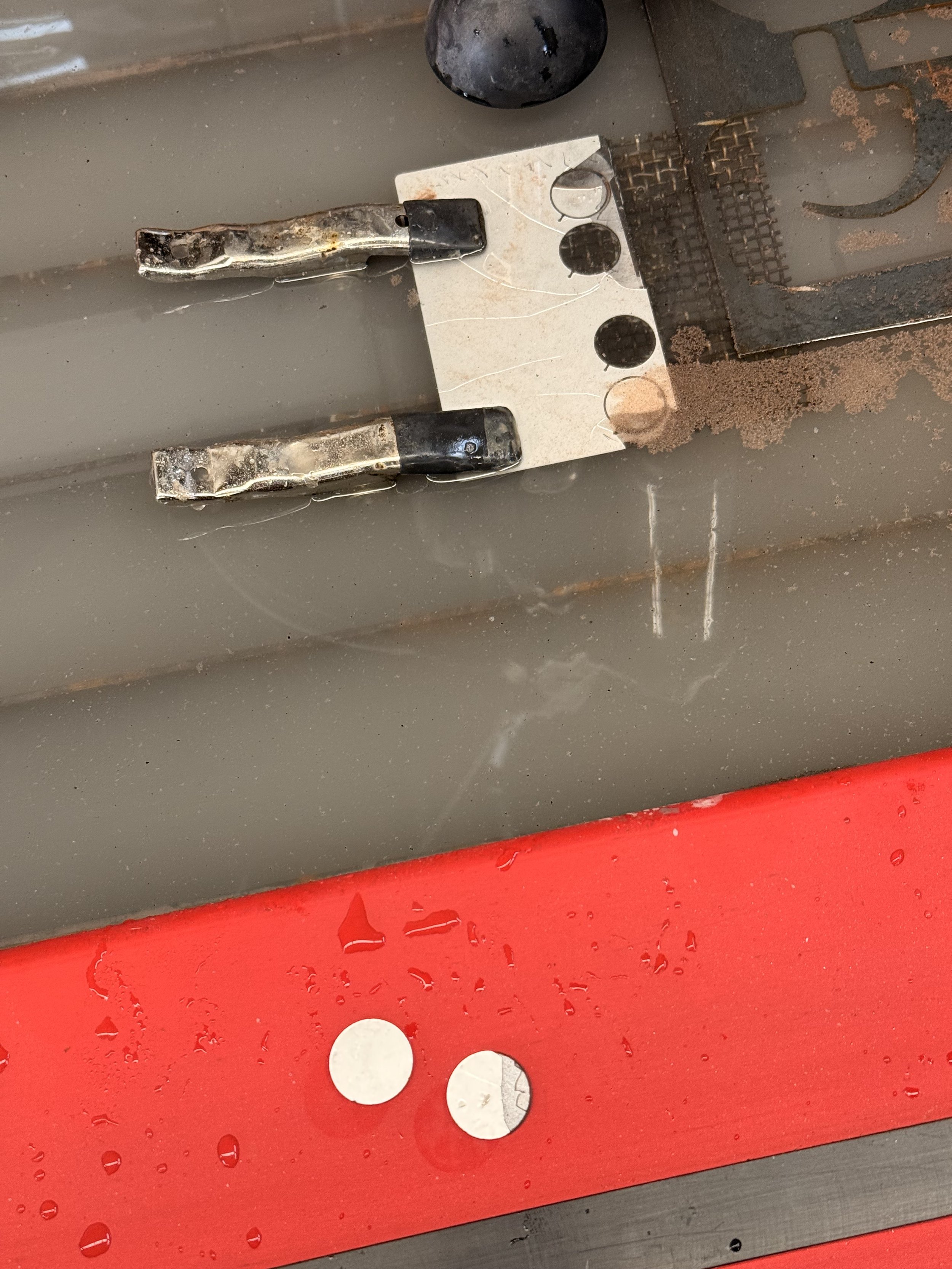
I then tried my lab’s newly installed waterjet cutter, which could apparently cut glass. After many attempts of adjusting power level, speed, and long lead-ins, all my test pieces still cracked.
Making a click
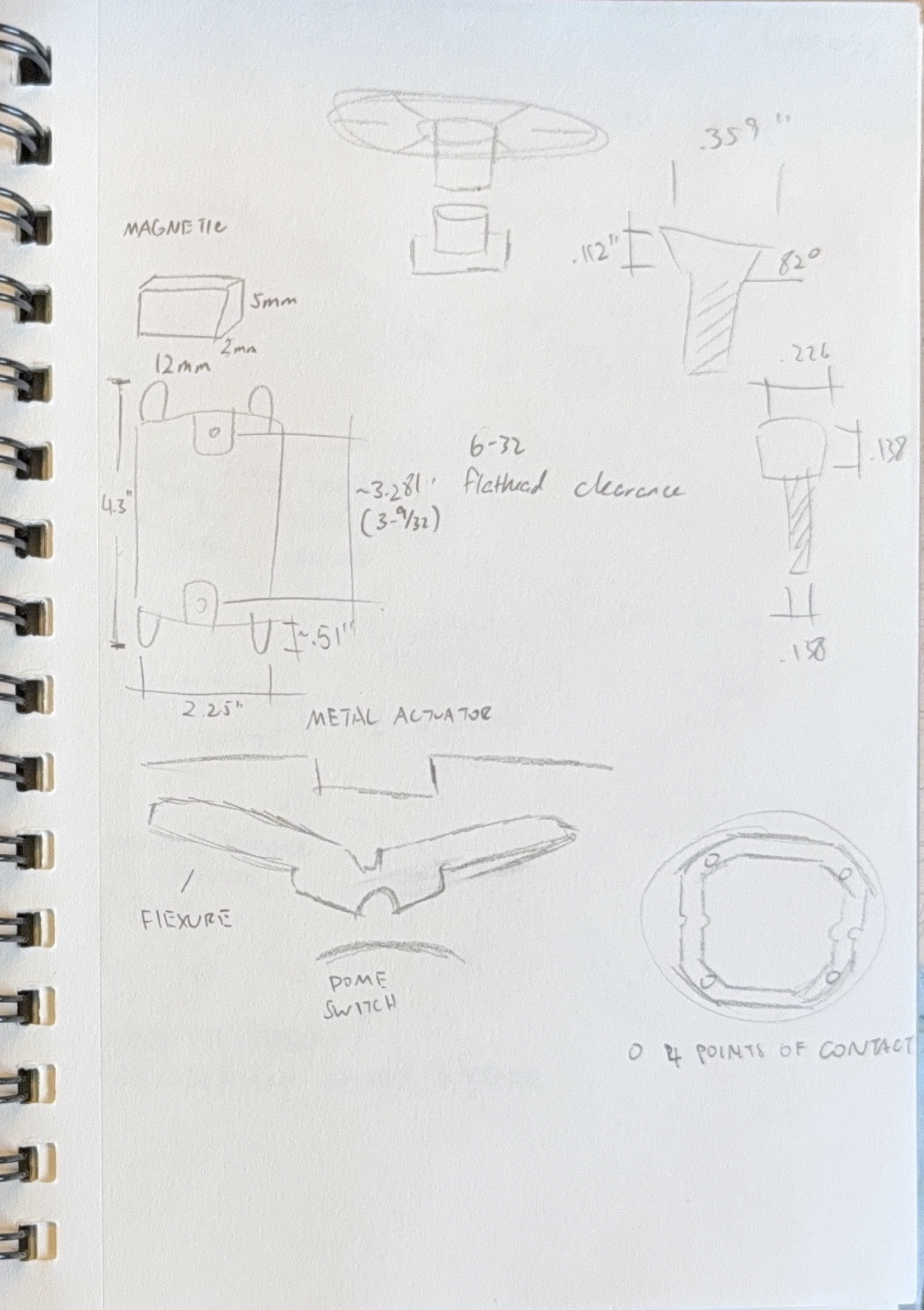
In the beginning I tried prototyping a flexure similar to the butterfly mechanism in my MacBook Pro. I wanted my button to have the same effort to click no matter where the user pushes on the body. It was quite complicated to dial in the right angles and thickness to get it to flex, so I abandoned that idea; maybe that’s why Apple moved away from it as well.
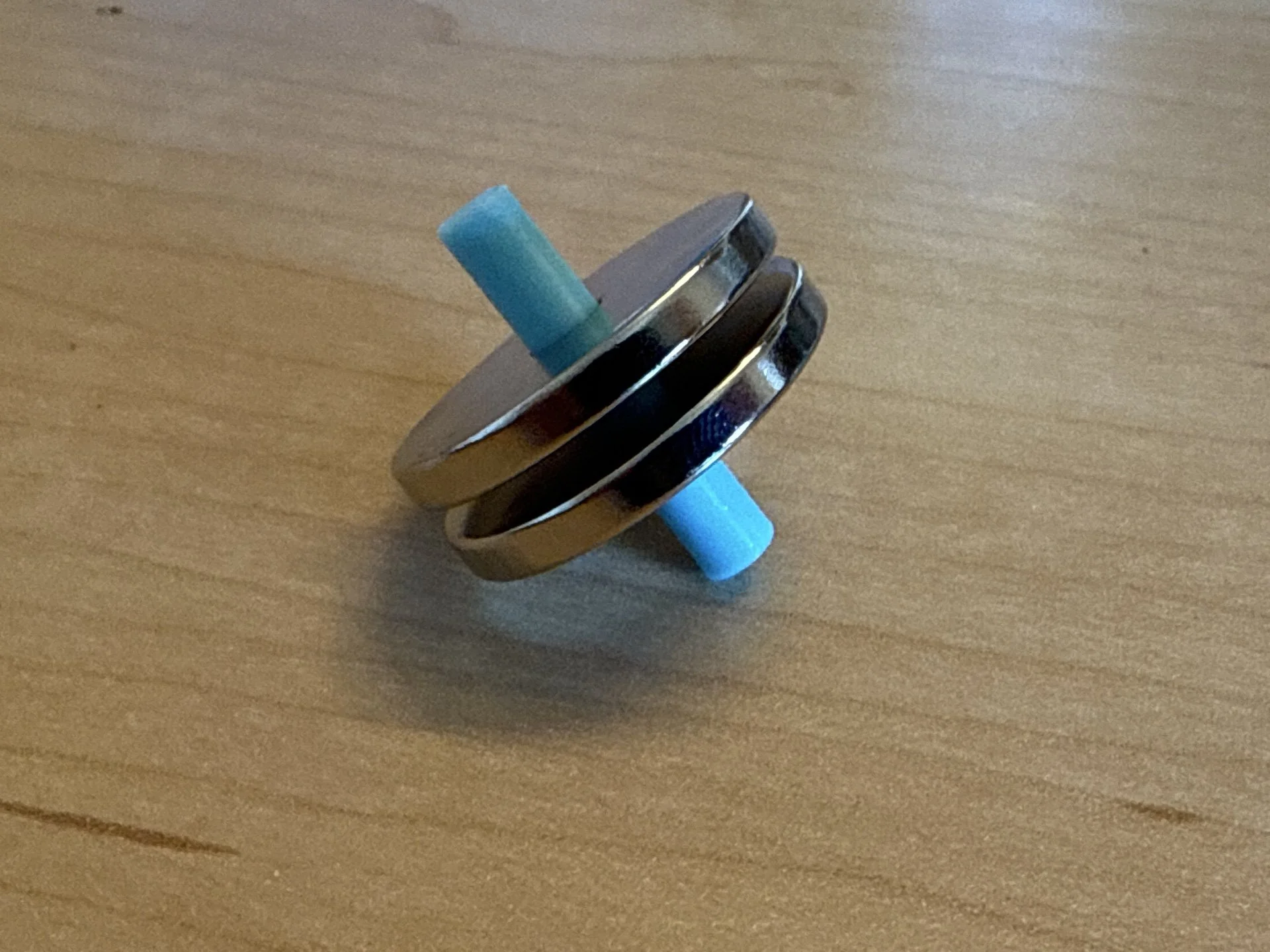
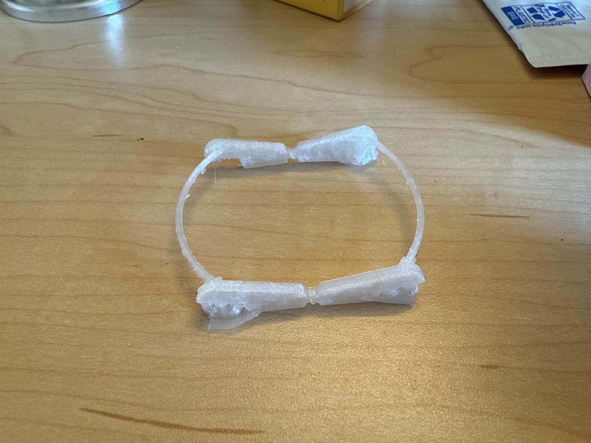
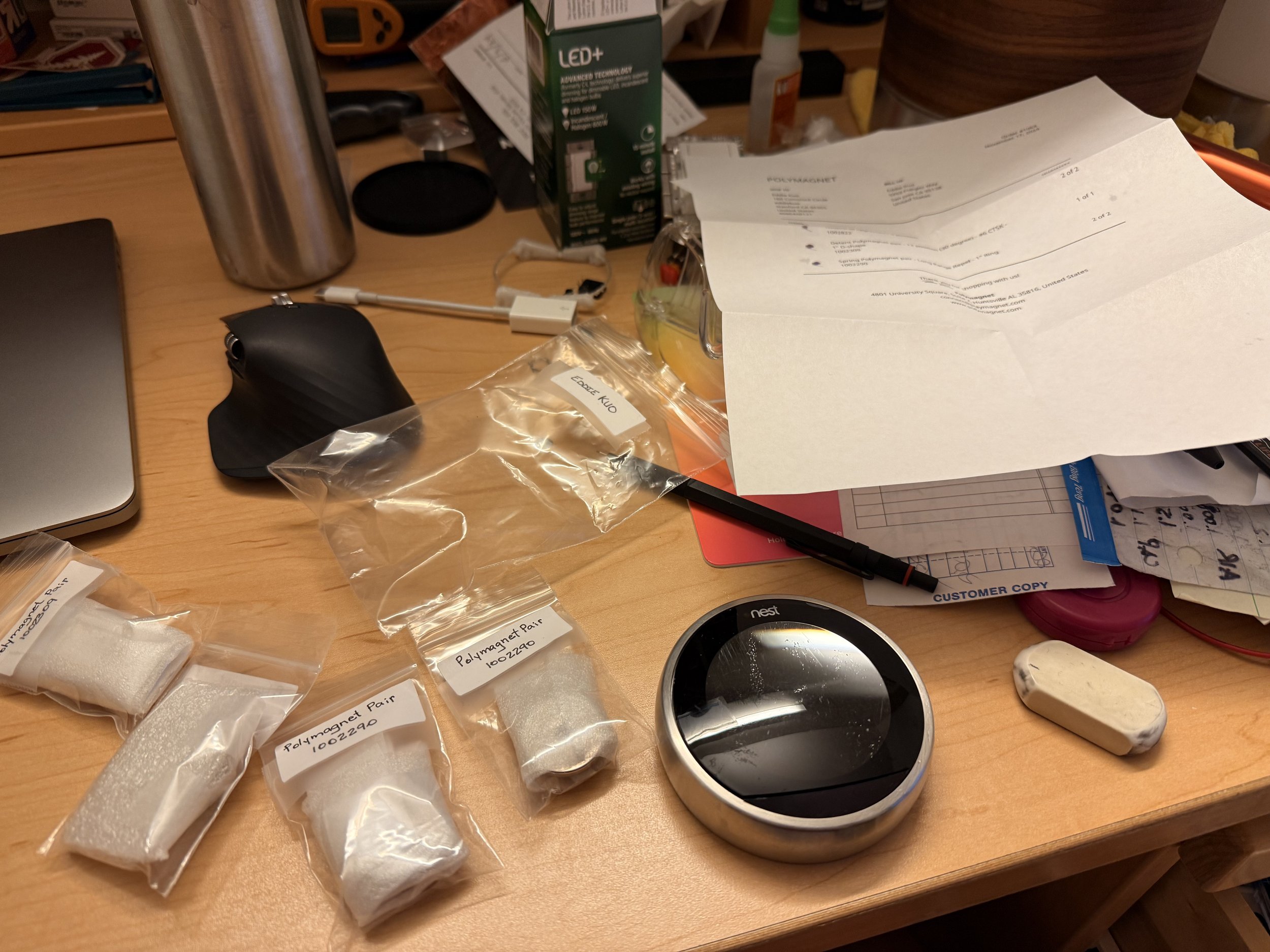
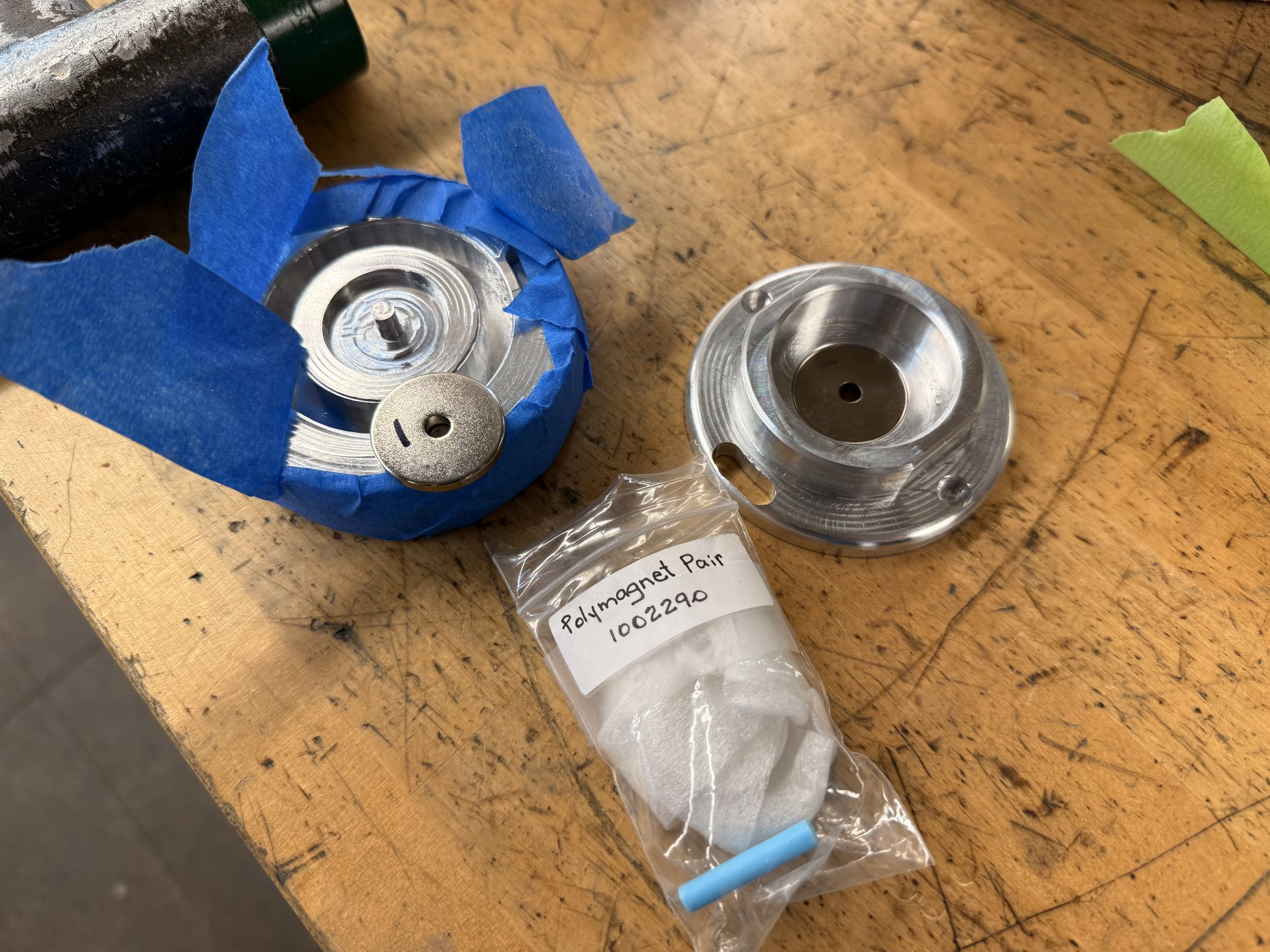
I needed a way to connect the main body and the wall plate while still have it act as a button. I also needed the machining setup to be simple. I recalled from an early science video about a special magnet called polymagnet, which allows the polarity to be customized. There was one that acted as a spring. It would attract until a certain distance then start repelling. I decided to use this as my spring for the button as well as a way to attach the body to the wall plate.
Machining the body
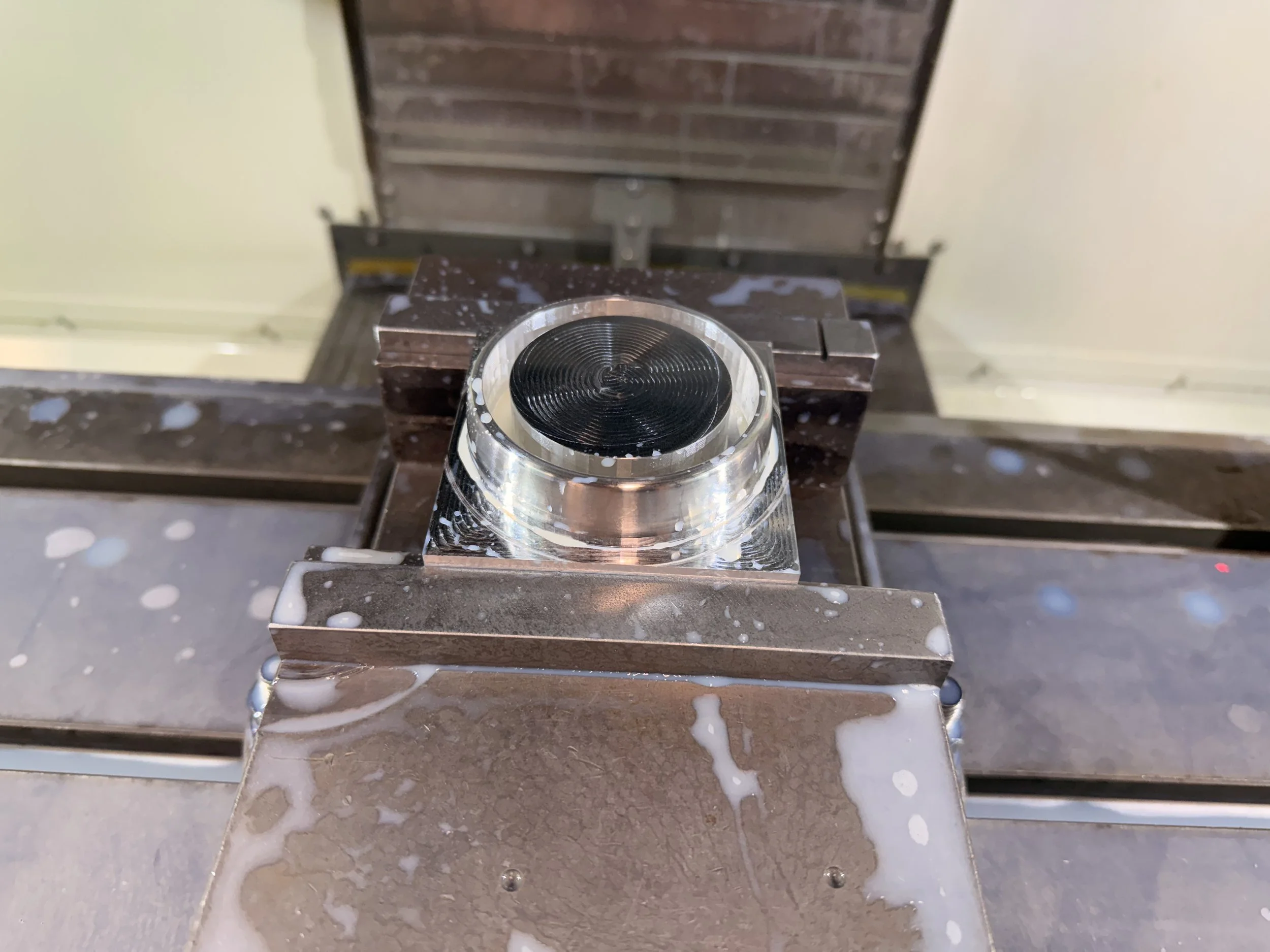
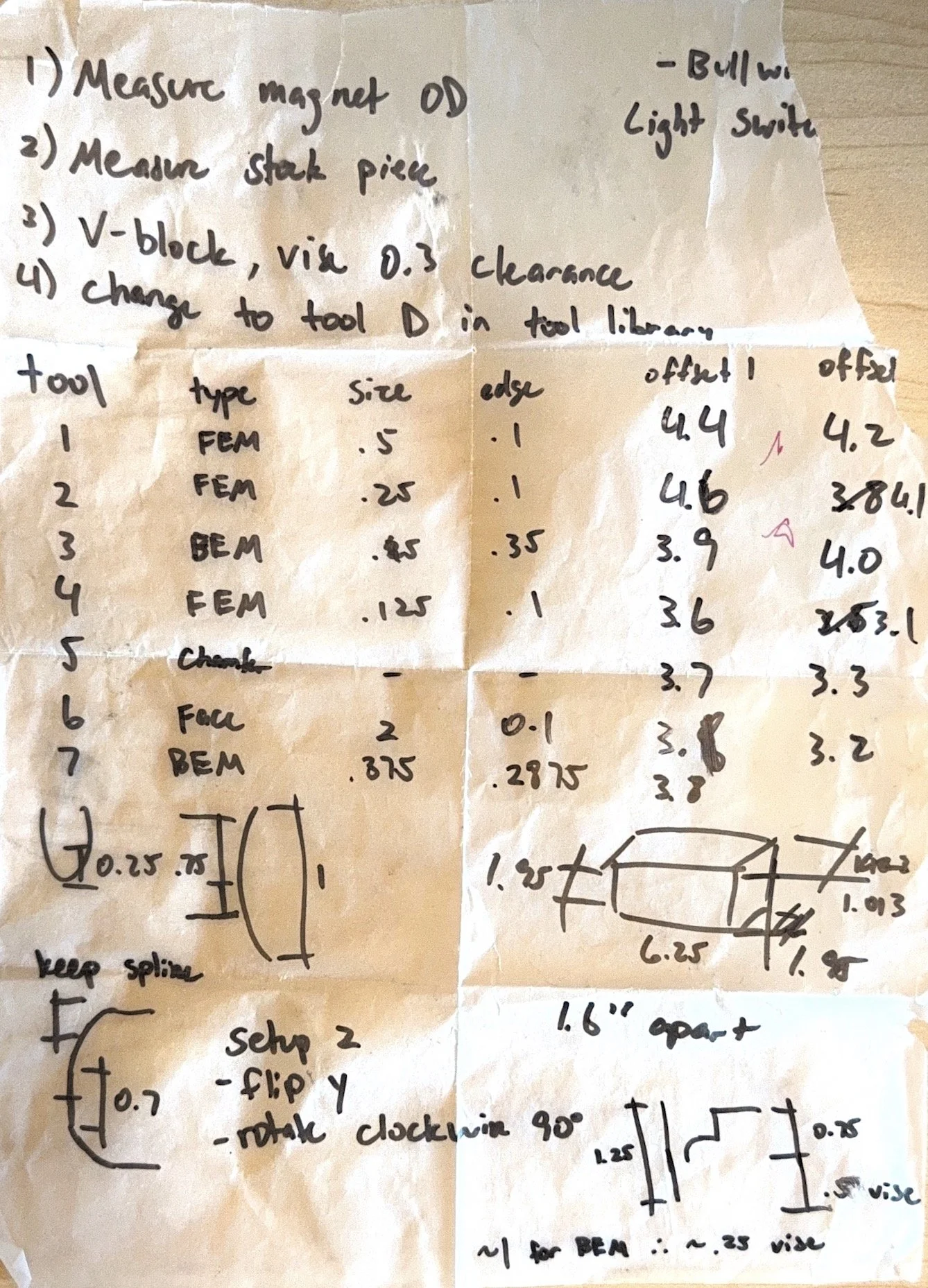
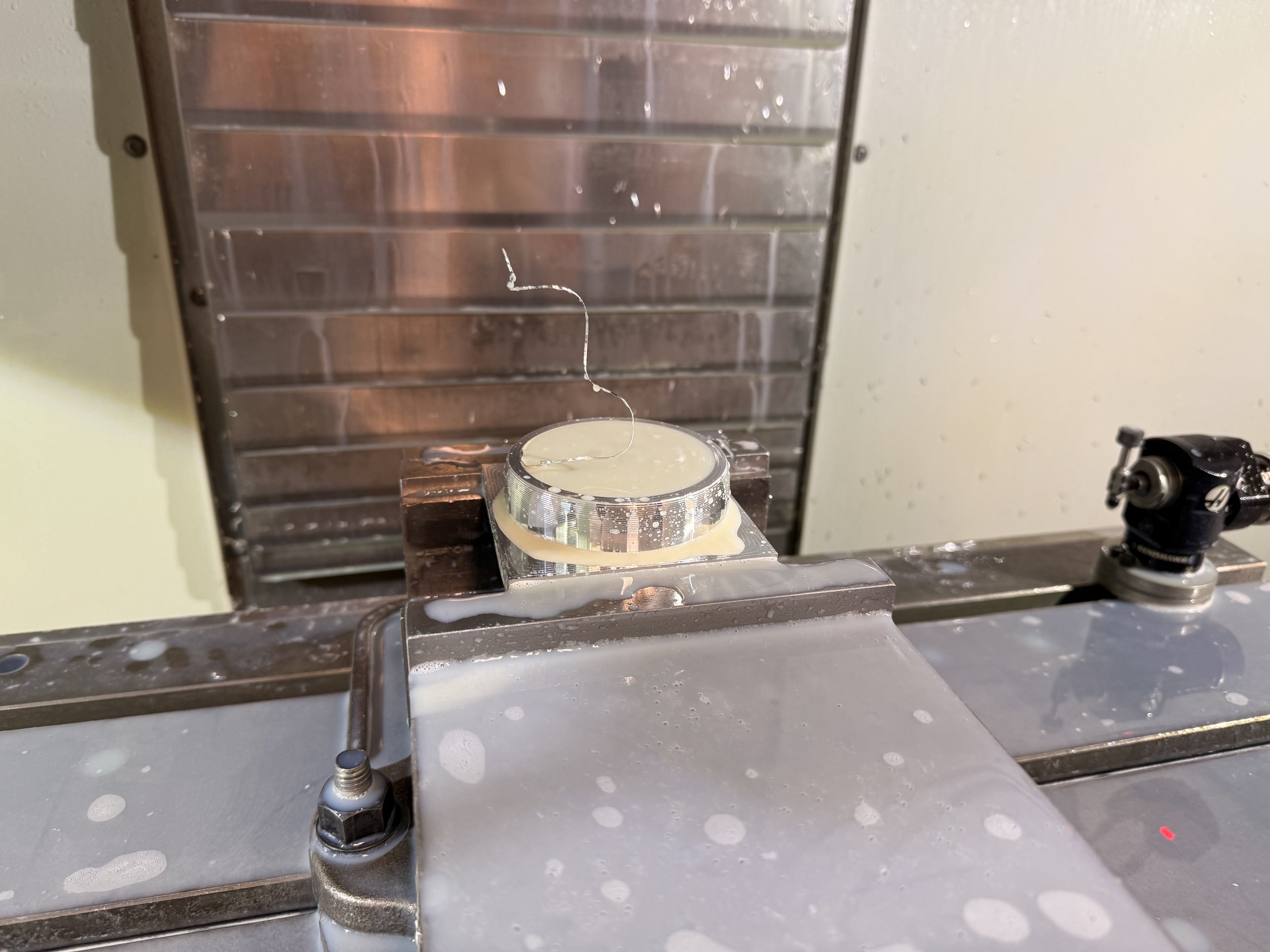
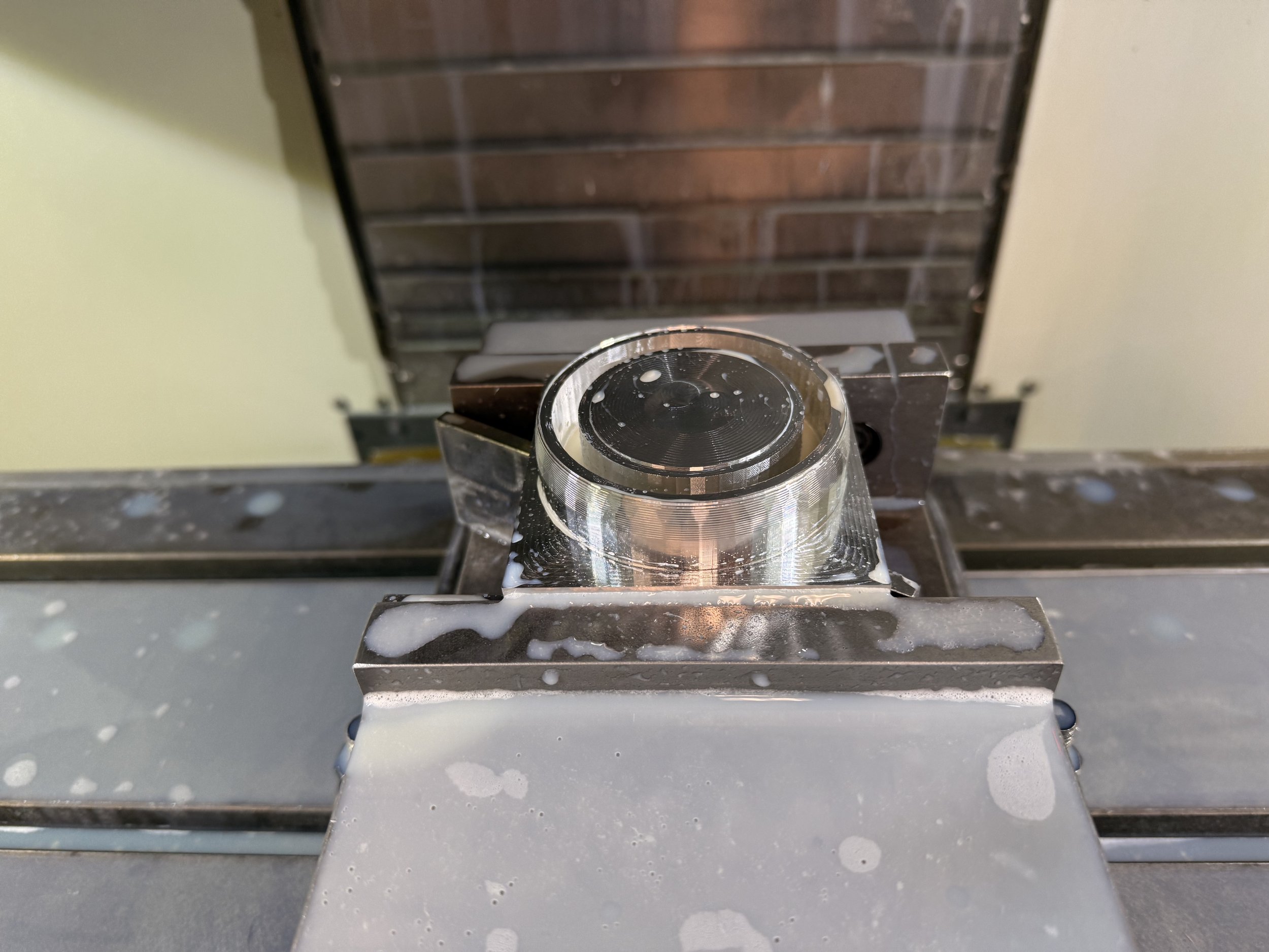
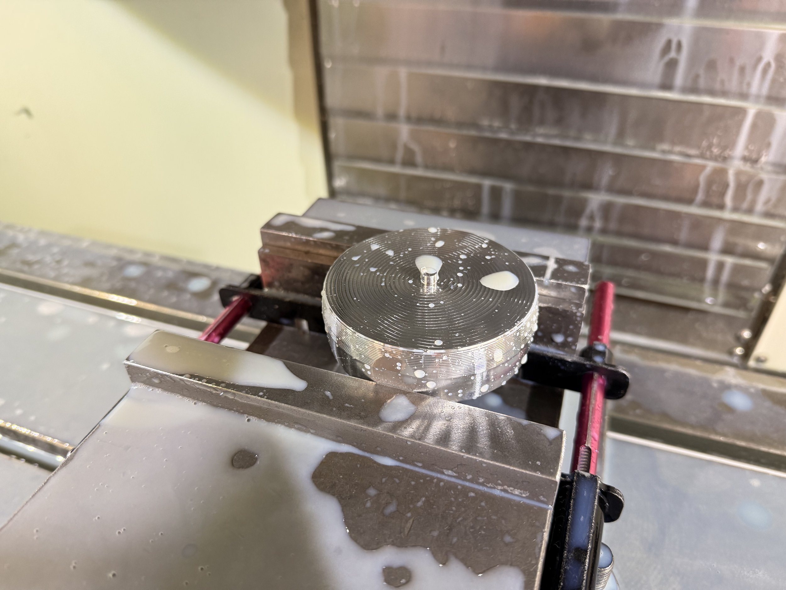
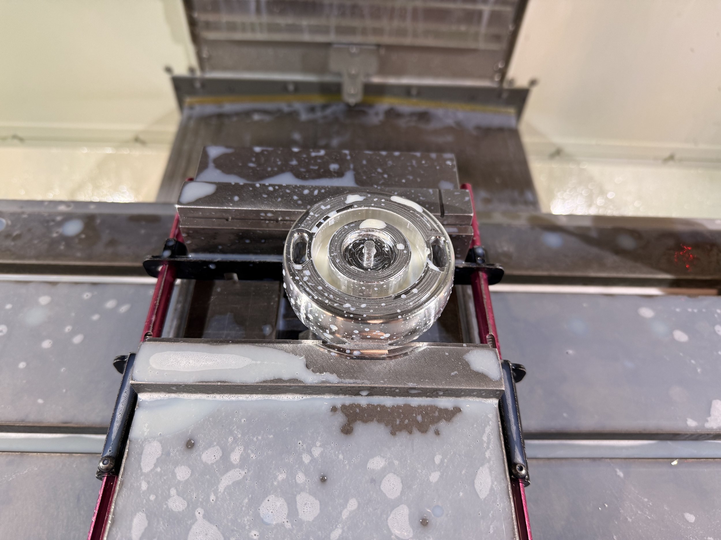
There was a lot to account for when machining the body. The body was initially a flat cylinder with the glass meeting at the very edge. However, limitations with the size of the electronics require some changes, so the exterior has a pillowed shape. This created a challenge holding it in the vise for the 2nd setup since all the v-blocks in the lab were either too small to hold the part or too high for the vise. Since we had a limit of 10 hrs scheduled machining time for the week, I had to think of a quick solution. I decided to add two small flats to either side and allow the vise to grip.
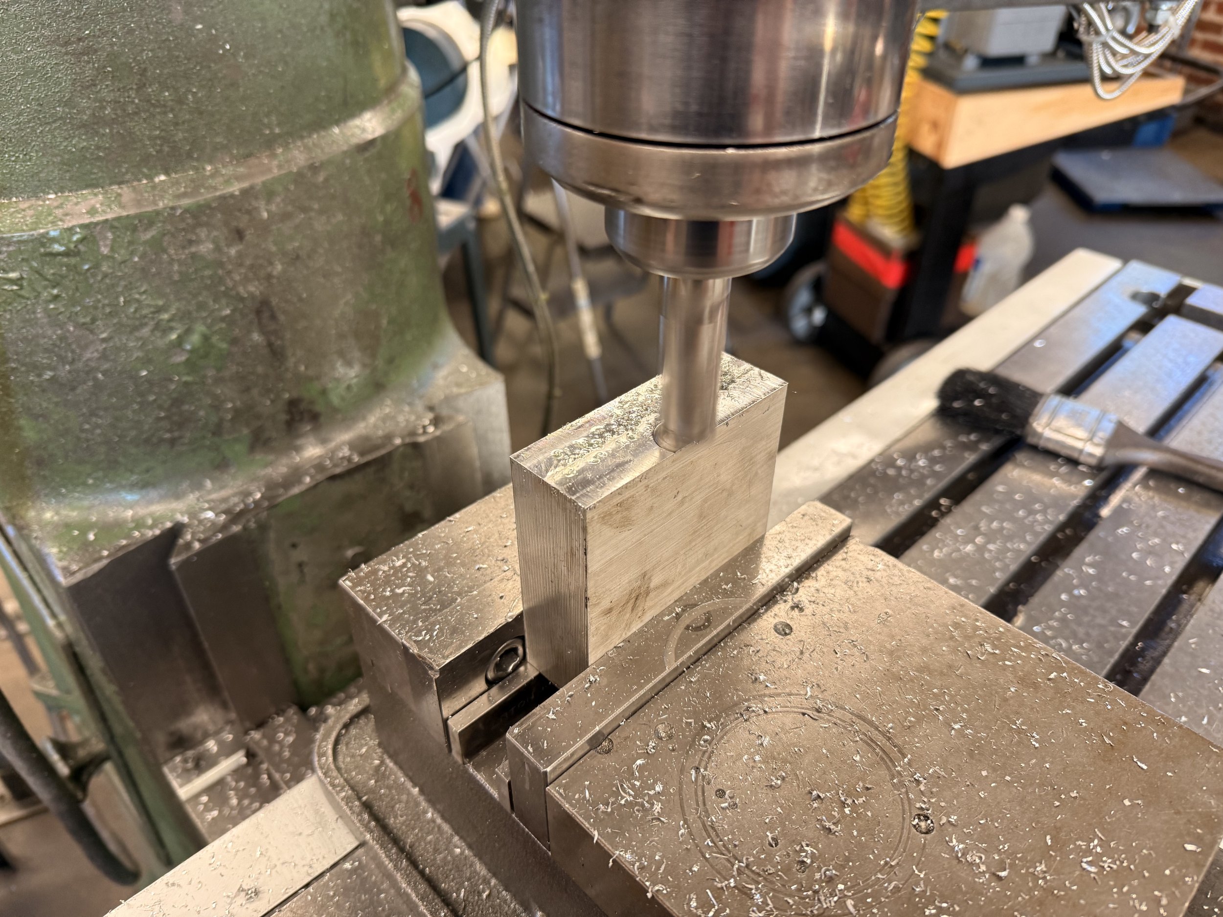
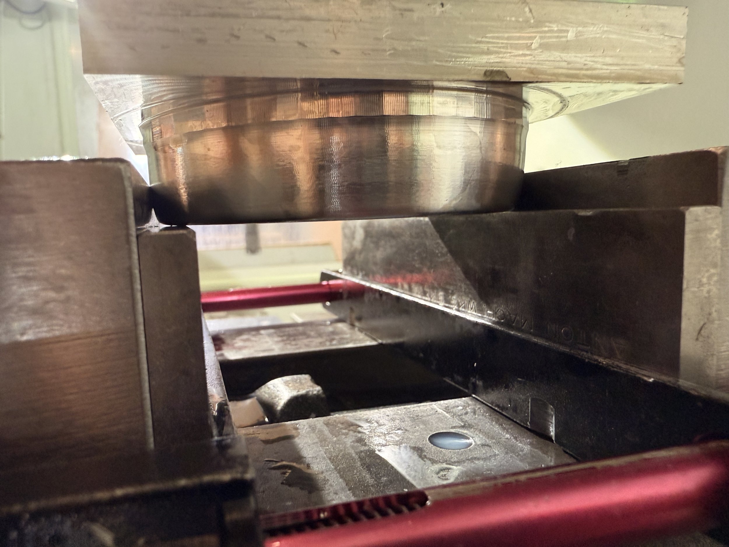
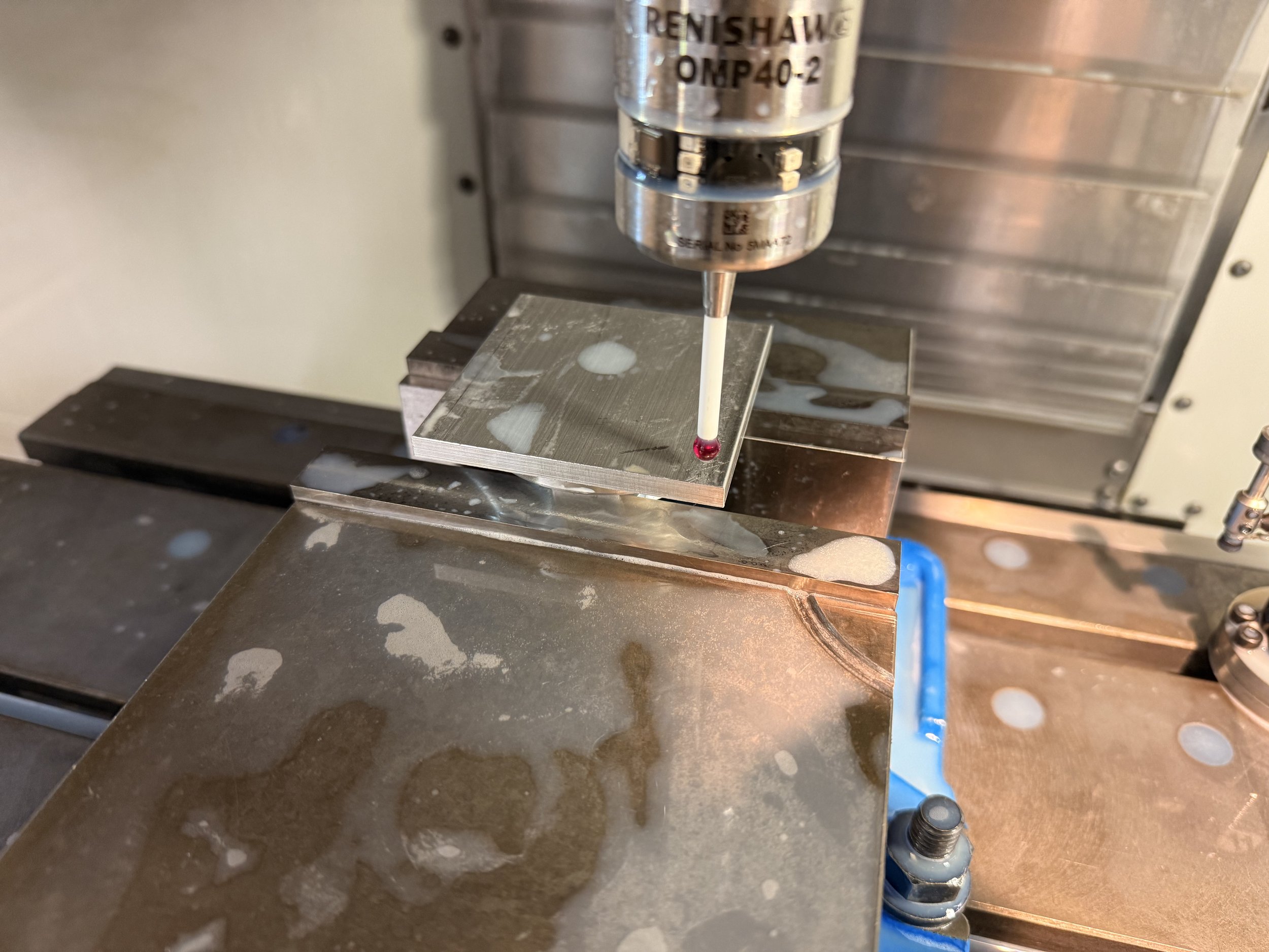
The height of the flat was also gutsy; I didn’t want it to be obtrusive so it left barely a difference in height between the tool and the vise. The part flip was also risky since my edge profile was a spline curve. The photo below shows that the edge barely contacted the xy plane of the vise. Any rotation along the y axis (tilt) would cause a wobbly line on the exterior band’s profile.
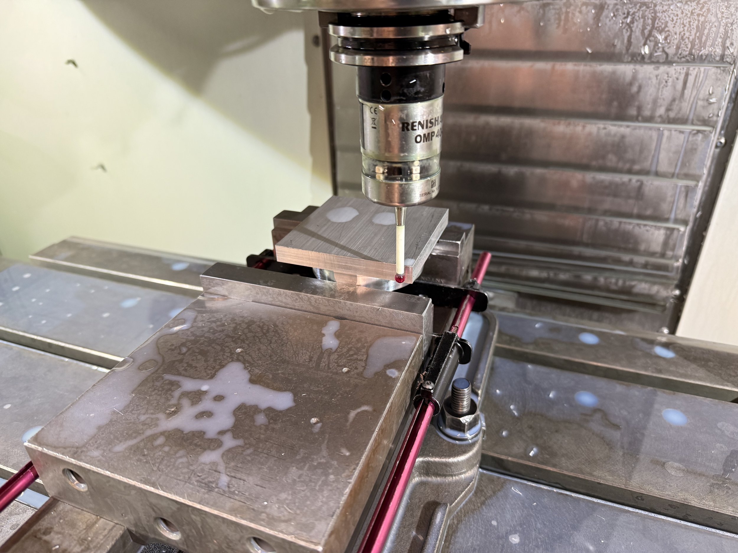
After careful probing, and inputting the measured tool diameters into my CAM, there was nothing left but to run it and let whatever happen happen. Part offset was my worst nightmare because I never found out what caused it for my whistle project. Relievedly, the pillowed band of the 2nd setup met up beautifully with the 1st setup.
Double check
I moved onto my 2nd part which was the wall plate. I learned a valuable lesson from my whistle project, which was how much more efficient it was to design features with the same tools; a lot of time can be spent loading and measuring tools before machining even begins.
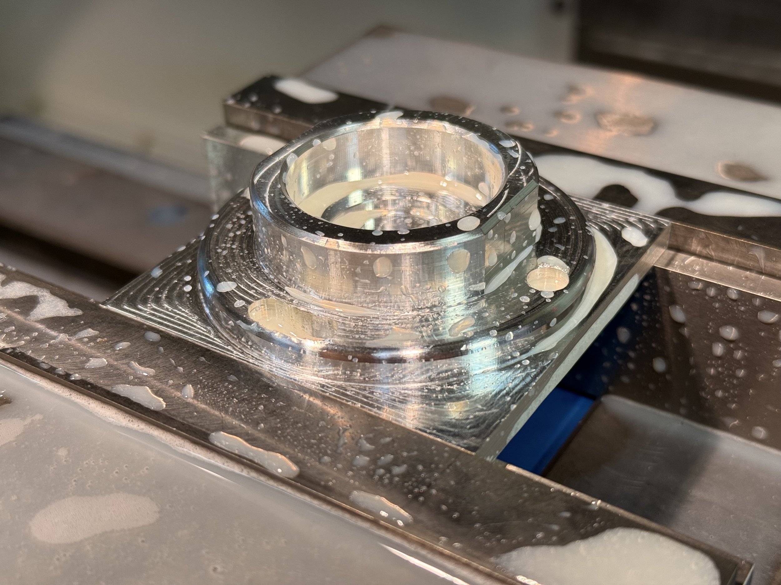
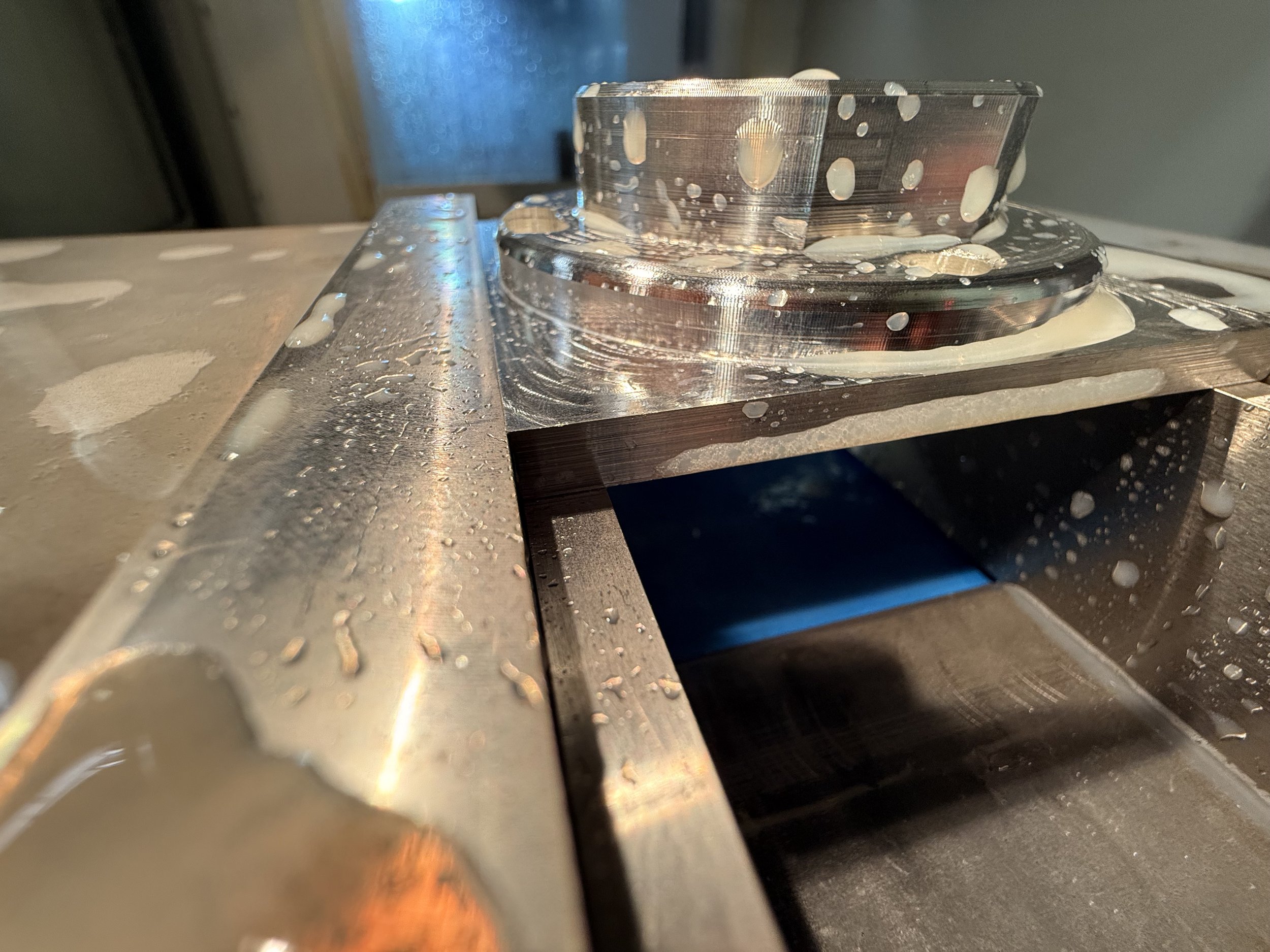
For my 2nd part, it was going great until the next to final operation of the 1st setup. I must have forgot to verify the simulation after some changes in my CAM, and the tool holder ran into my part when drilling the holes. It was a good thing I decided to purchase two stock-pieces for each part so I was able to easily remedy that.
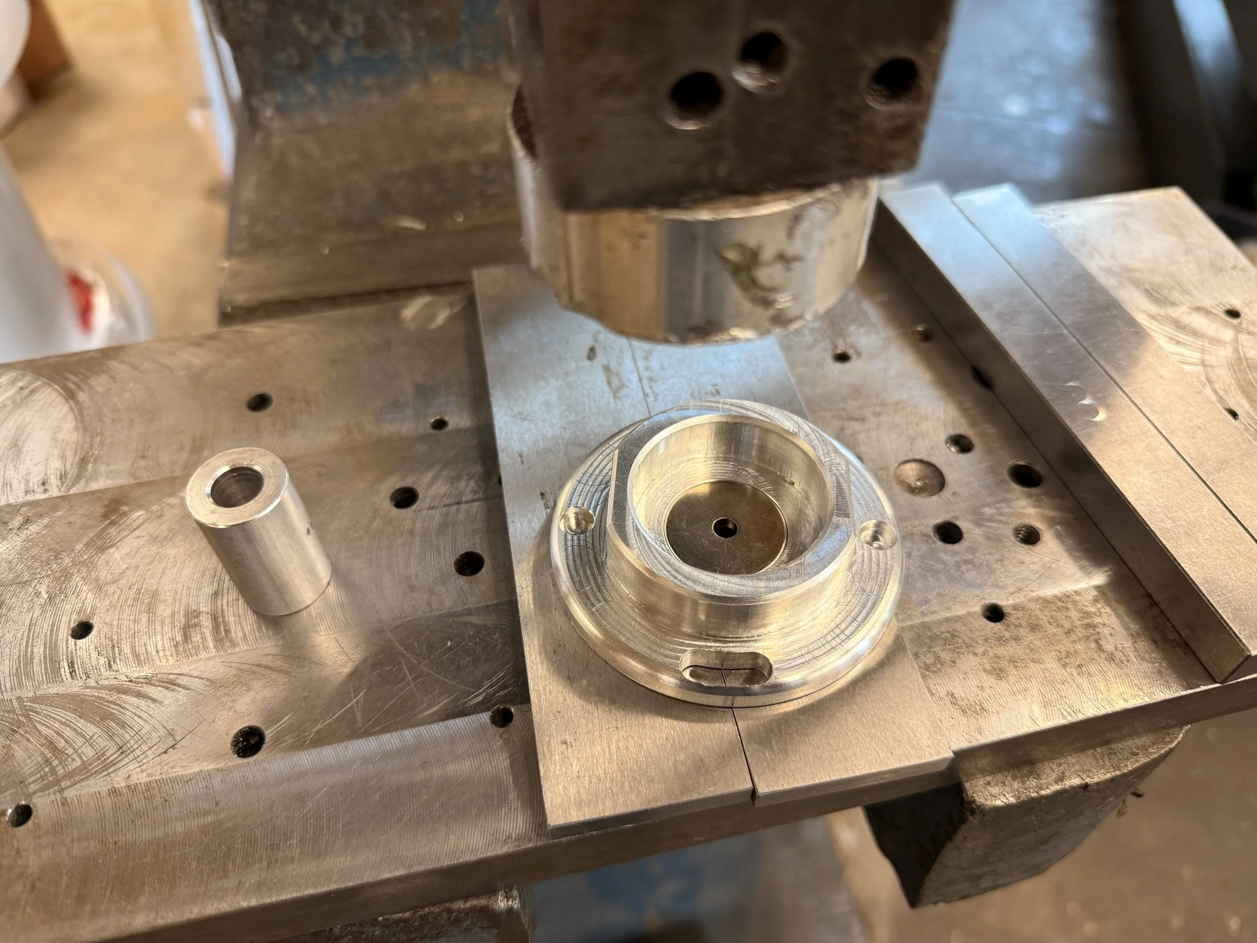
I also had to face the stock pieces off so the height varied a bit. From the photo below, after running the first setup’s operations, it was unbelievable to see that the stock piece was just a hair taller than the vise — it remained completely unscathed.
Quick fix
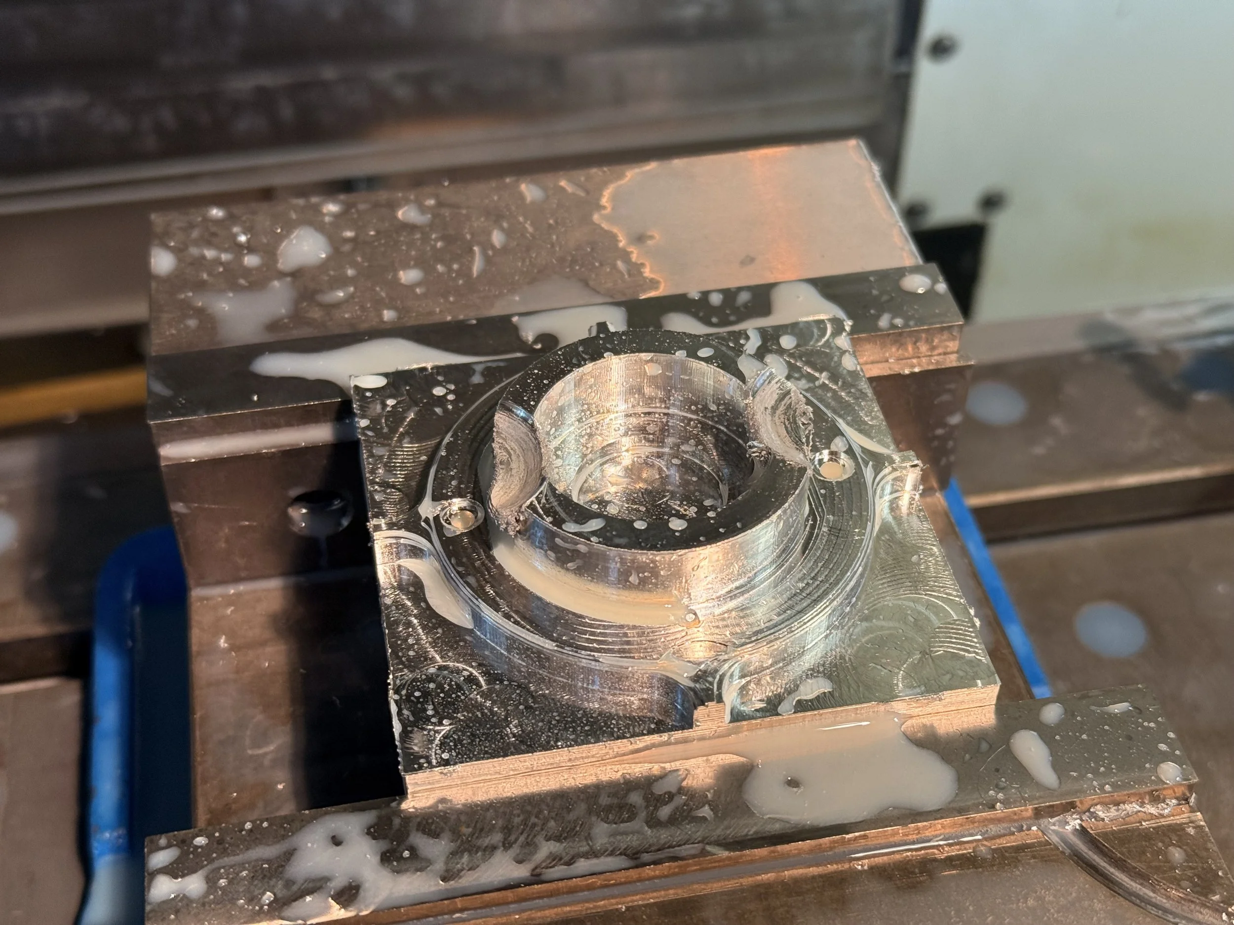
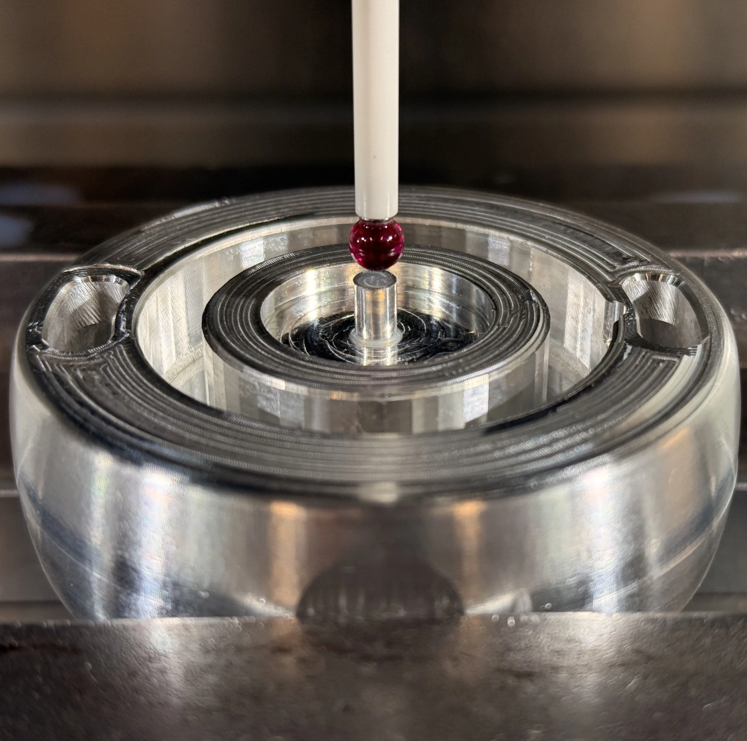
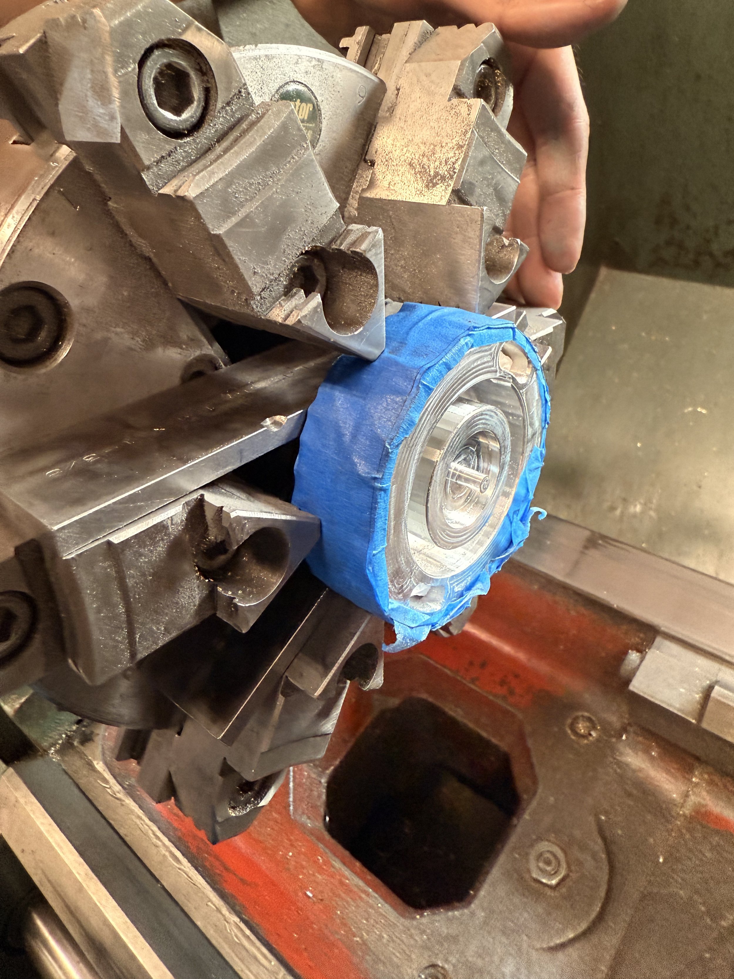
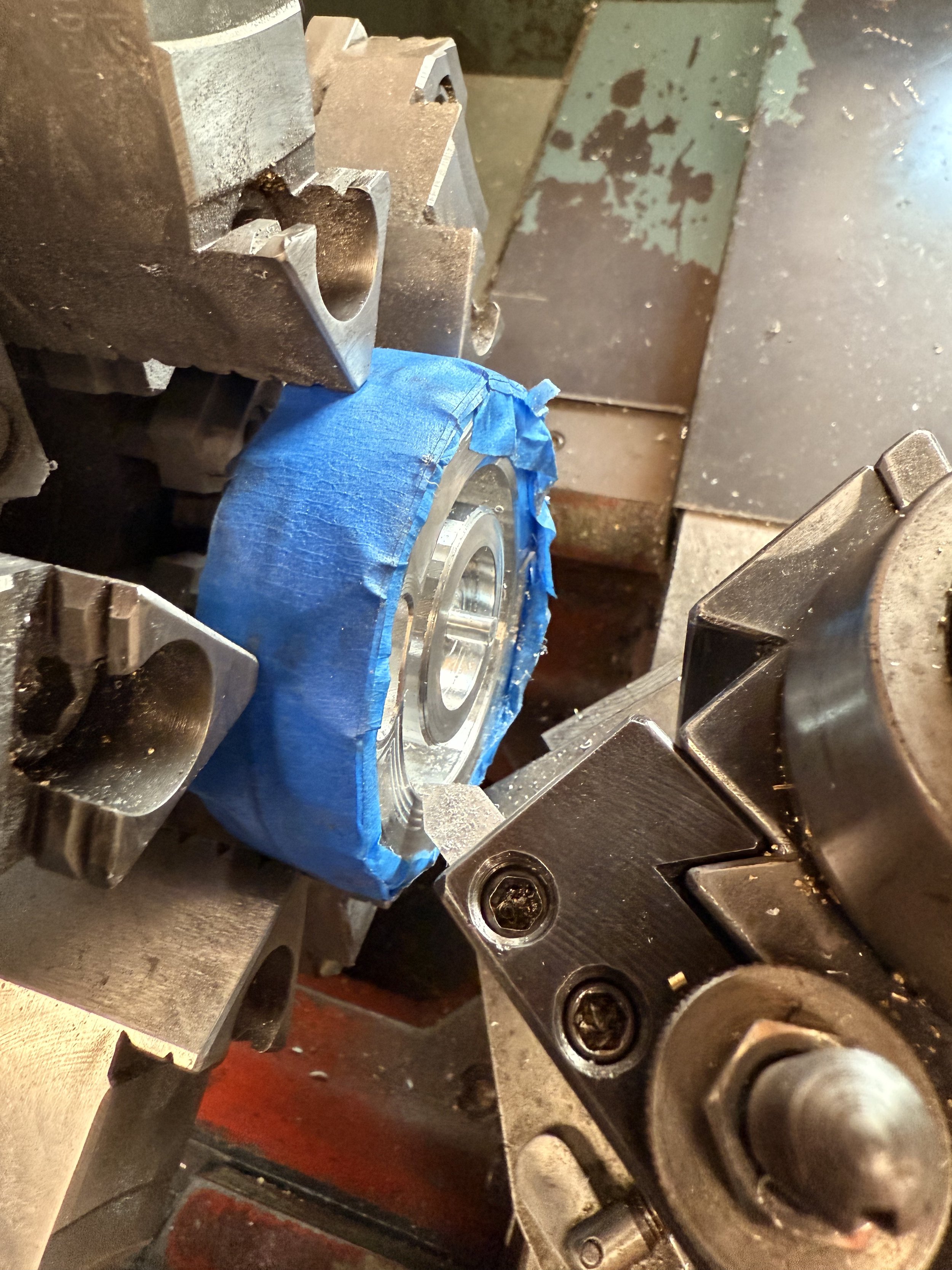
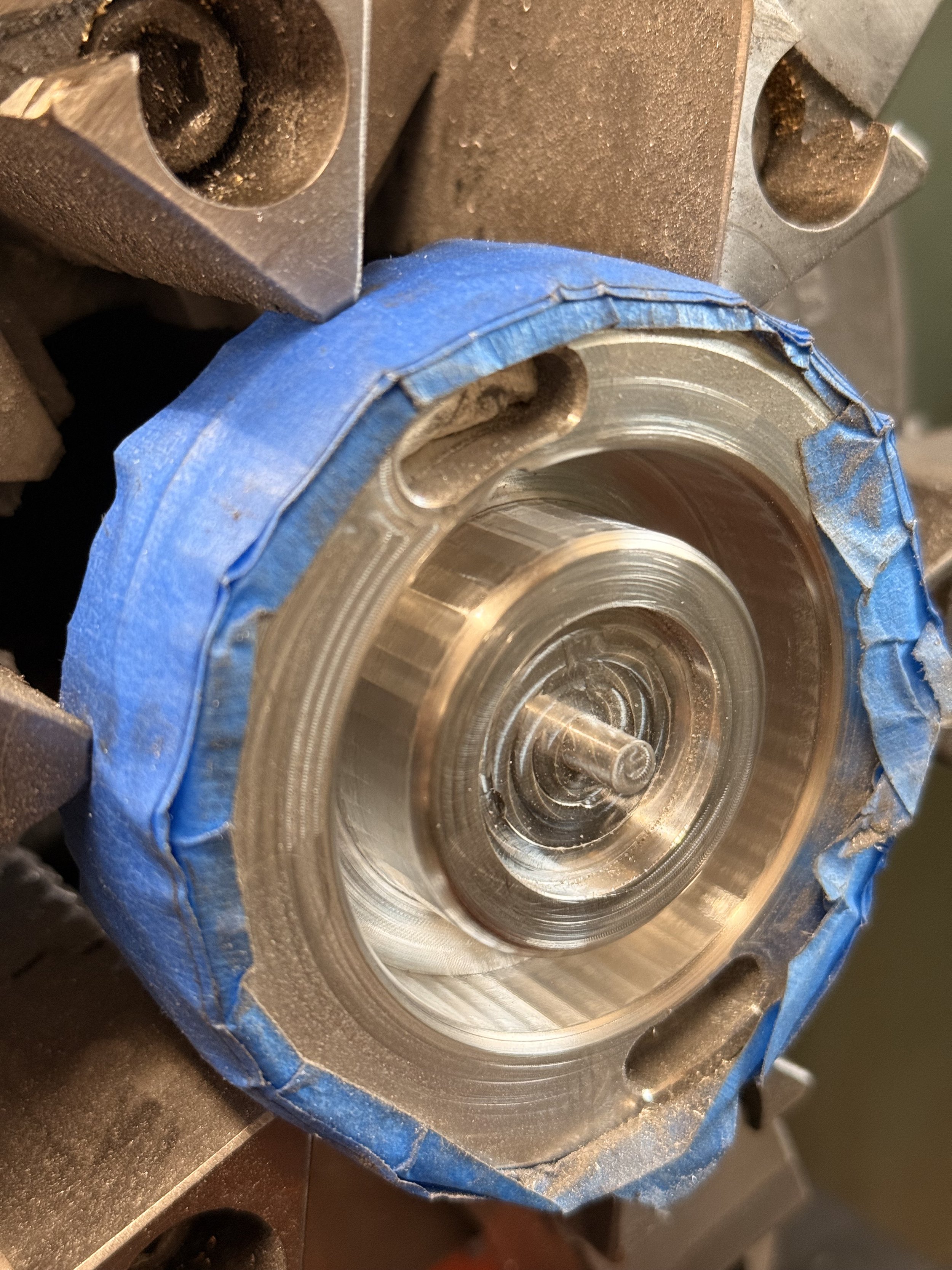
Unfortunately for my first part, I accidentally chose the ball end mill for my flat operation instead of a flat end mill leaving cusps all around. There was an open machining spot that evening, so I took advantage of it. I decided to probe my part with a cylindrical boss. Oddly enough, the probe was a bit off axis even after multiple attempts. I decided to run it and shave off the cusps conservatively to prevent it from accidentally nicking off the stem.
I adjusted the z-height several times, but it was too risky since I could not get any visual feedback once the coolant started flowing. I decided to wrap the edges with painter’s tape, prop it up on some parallels and turn it on the lathe.
Main body finishing
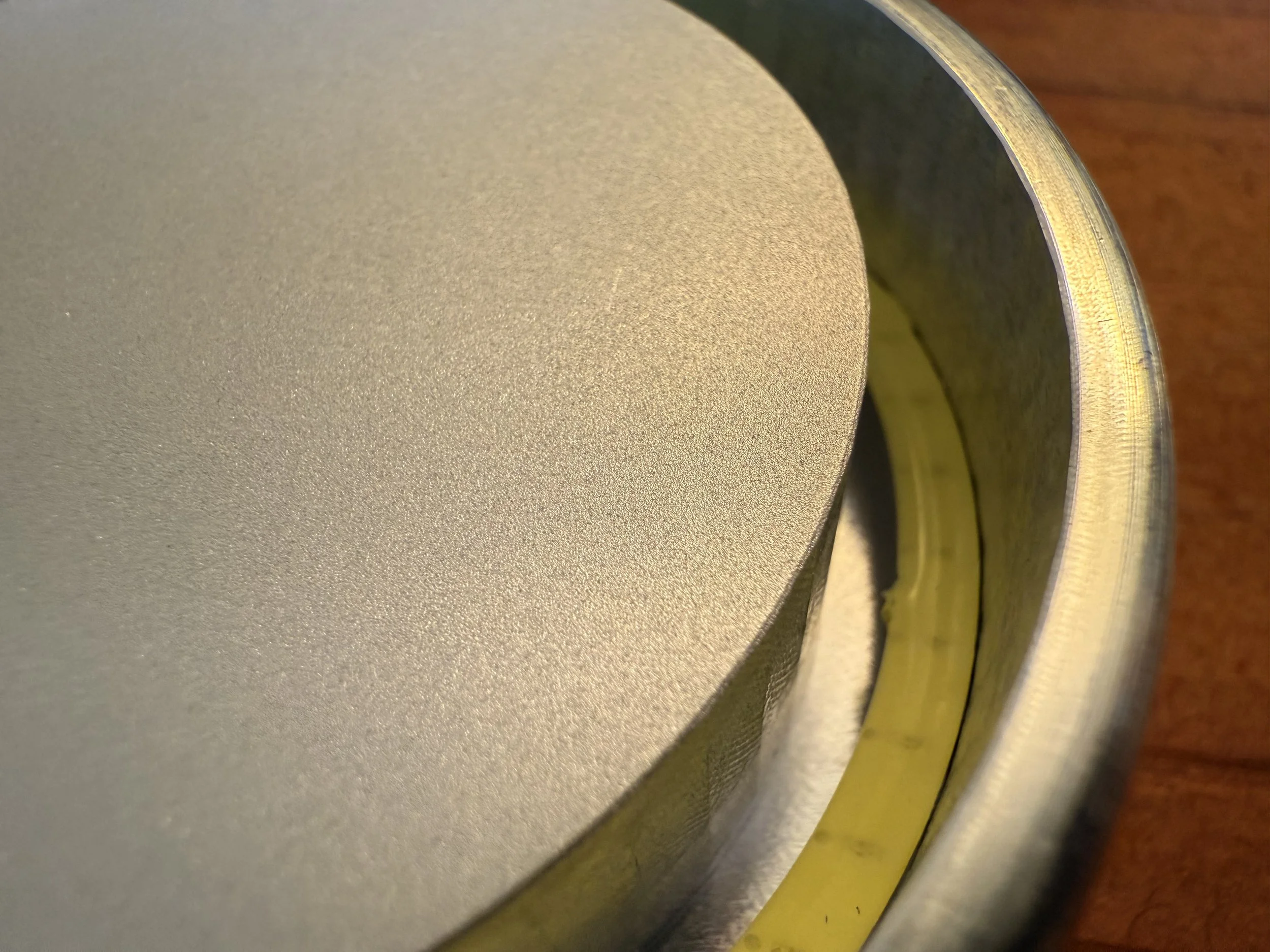
I wanted to keep the machined finish of the CNC for the body of my part. I believe that’s a valuable feature especially on the 3D contours of the product. The only part I want extra finish on was the center where the cover glass rests on. When the glass is pressed against the surface, it will see a smooth bead blasted finish that mimics the texture of the cover glass itself.
Wall plate finishing
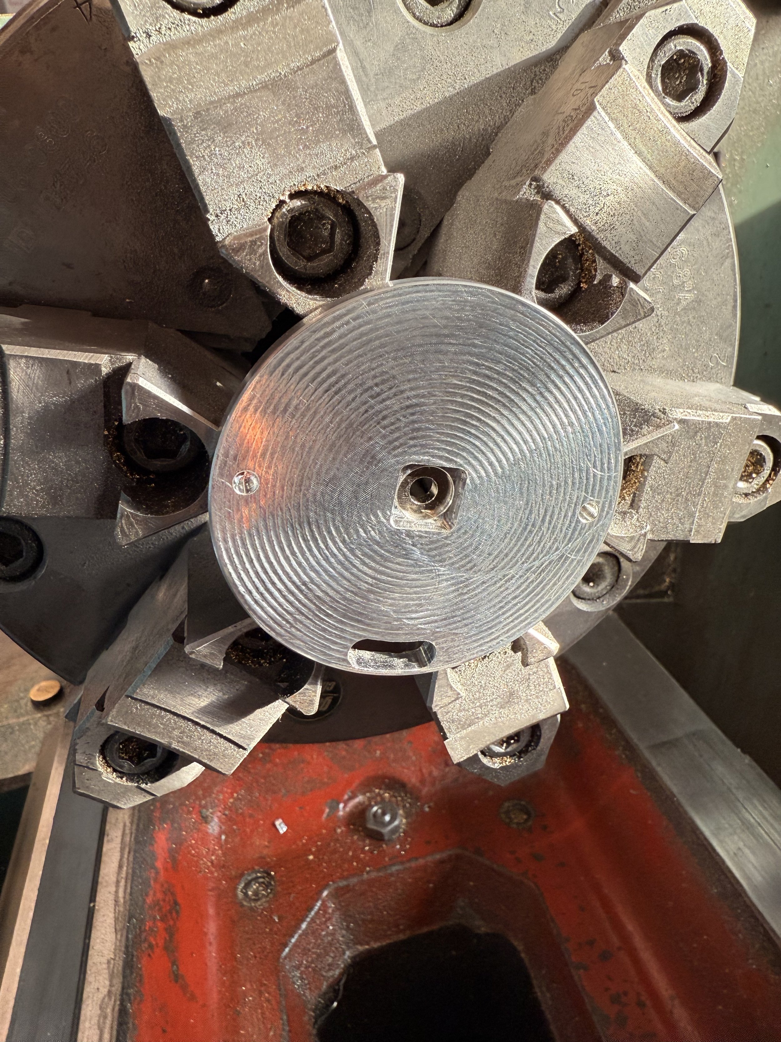
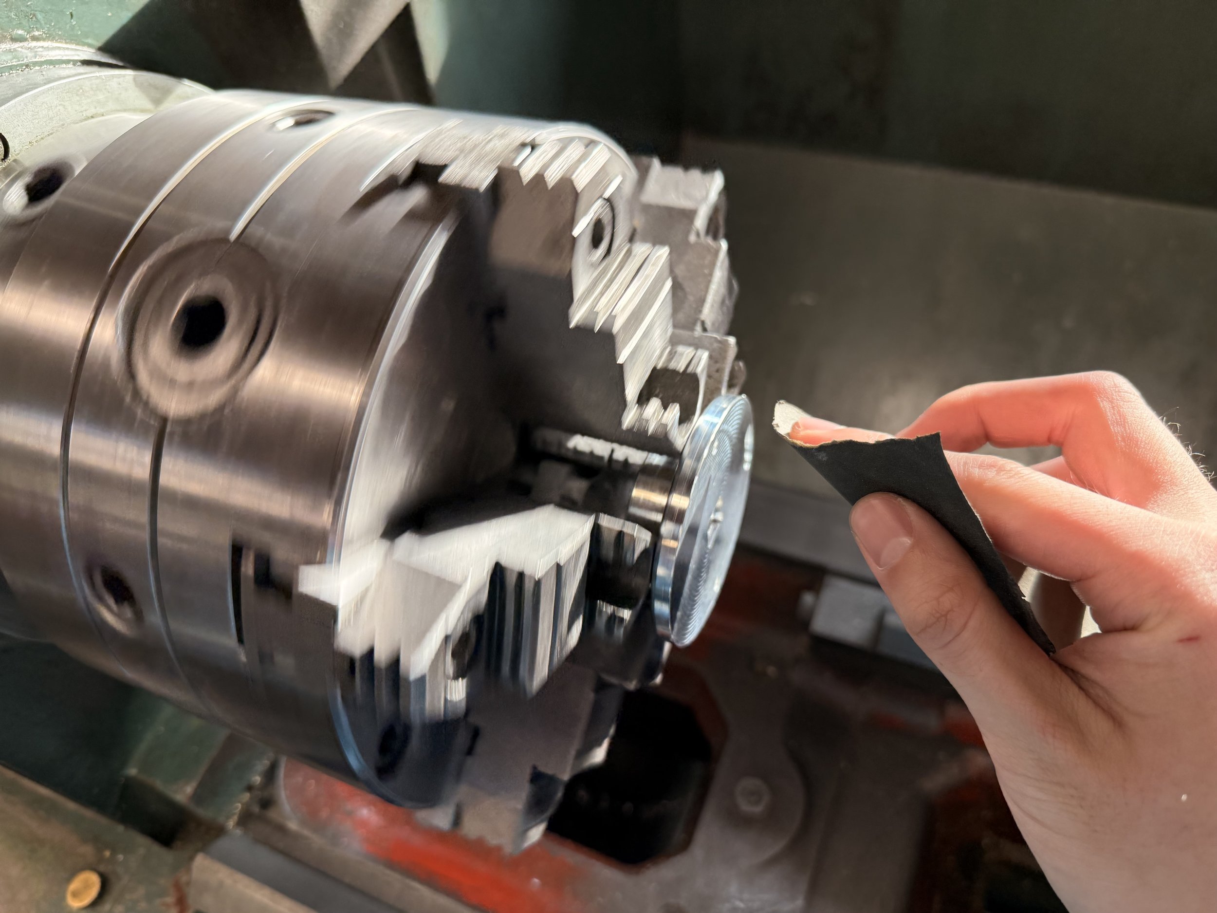
Again, I wanted the CNC’s machined finish to shine through. Although only the edge of the wall plate is visible, I personally believed it was important that the backside of it was nicely finished as well. I used a spiral operation with the flat end mill with a smaller step over than that on my whistle’s air seal, but they still didn’t turn out as nice as I wanted. I decided to sand it up to a 1000 grit on the lathe to get a nice smooth radial finish.
Joining magnets
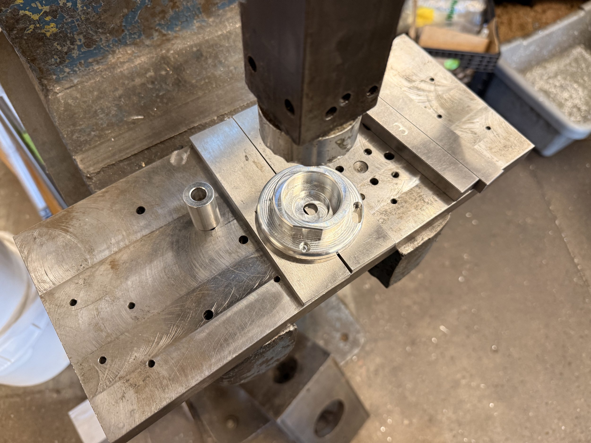
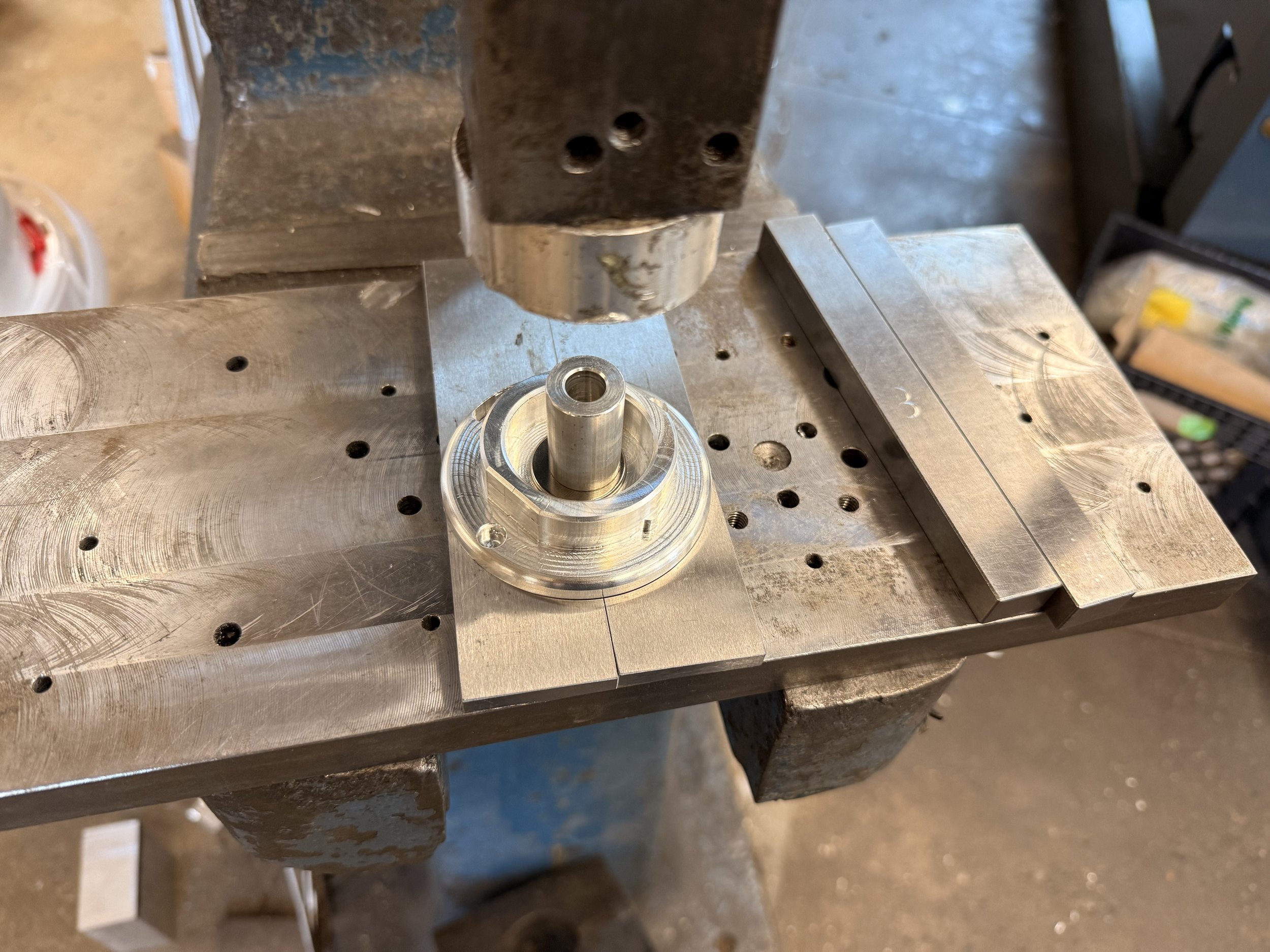
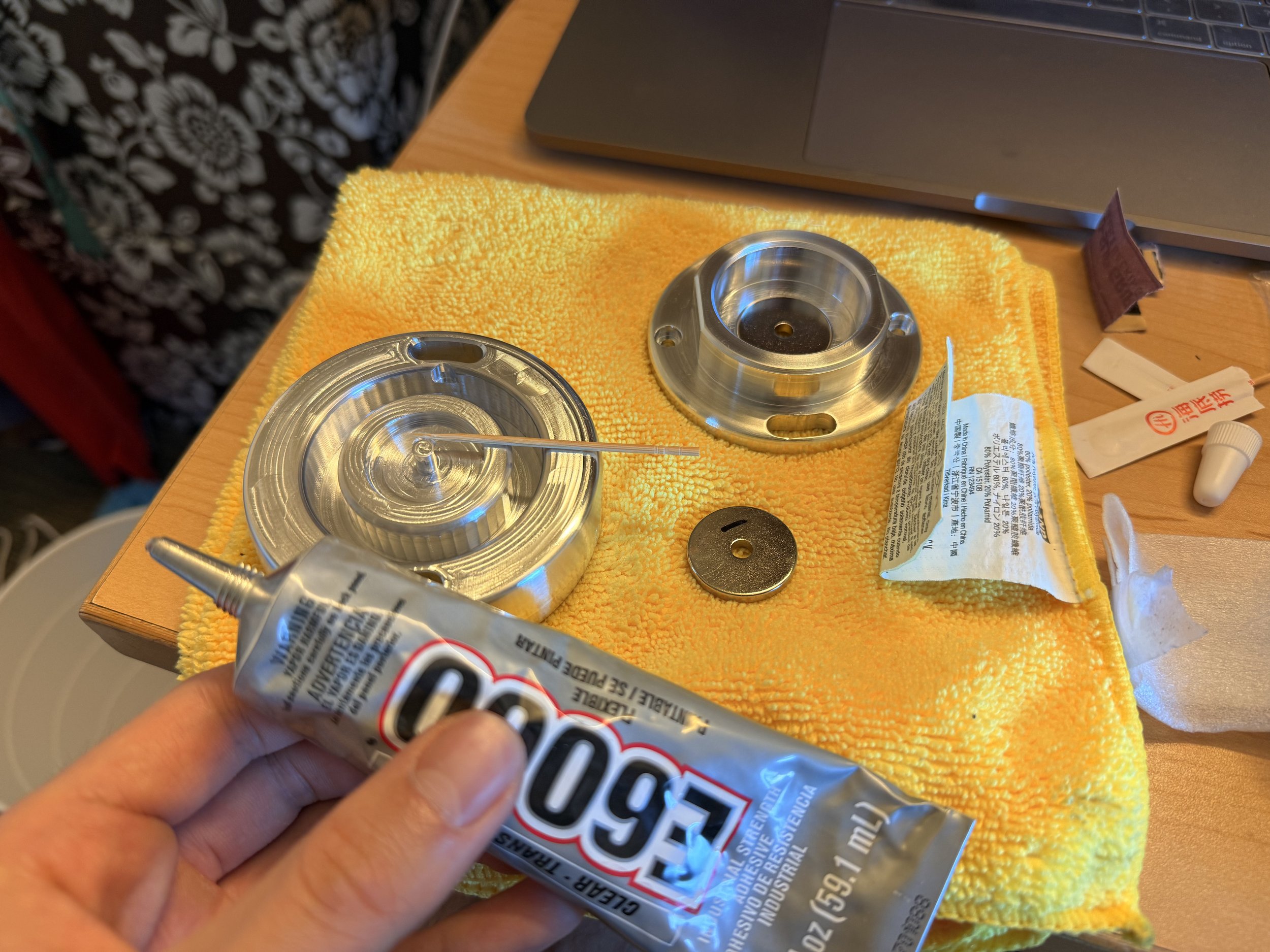
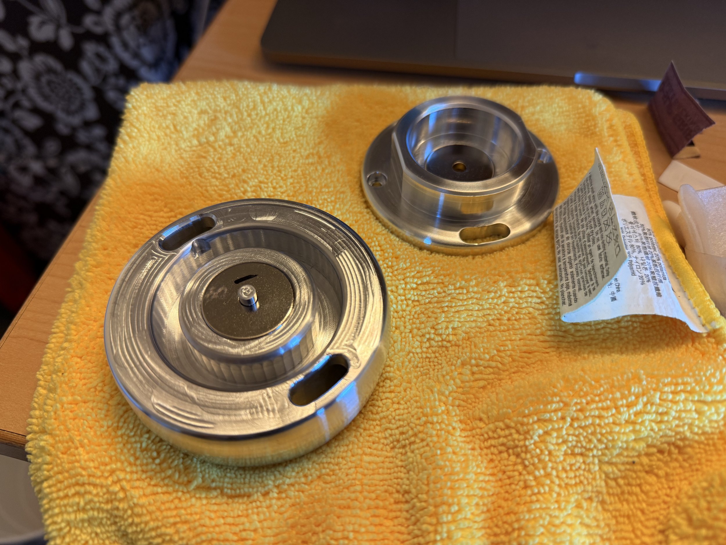
It was time to put the magnets in. I made sure to measure the diameter of my magnets with calipers to account for variations, and there were variations between the two. Even though I inputted them into my CAM, and accounted for the measured tool diameters, it kept the one on the wall plate a press fit but the one on the main body became a slip fit.
I know that magnets are brittle so it could be risky to use the hydraulic press to press it in, but I did see one person press fit magnets into their metal just fine, so I went for it. I found a found a little tube just smaller than the diameter of the magnet and pressed it. It sat nice and flush in the wall plate.
As for the main body and the 2nd magnet, I used E6000 adhesive to join them.
Diffusers
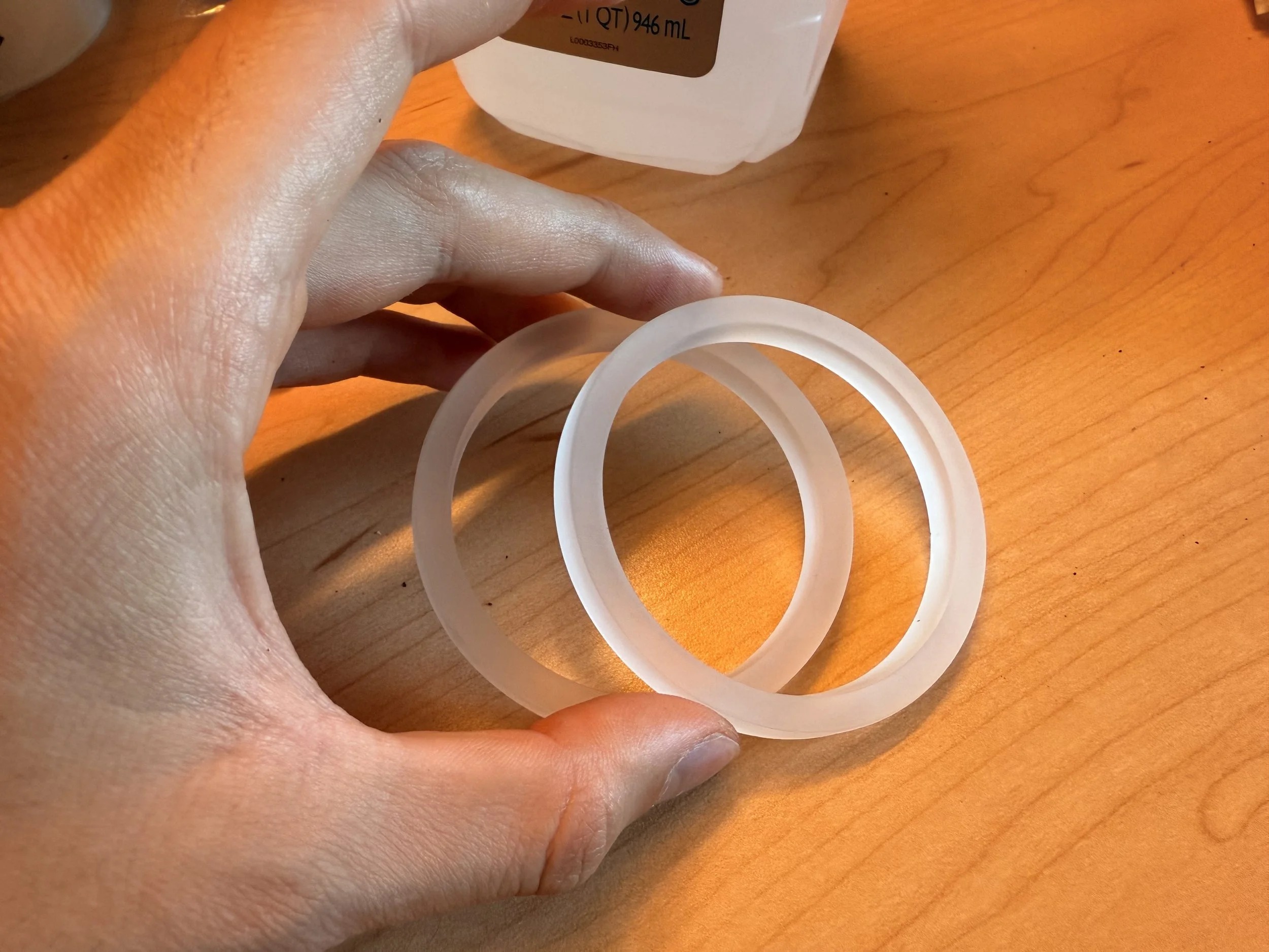
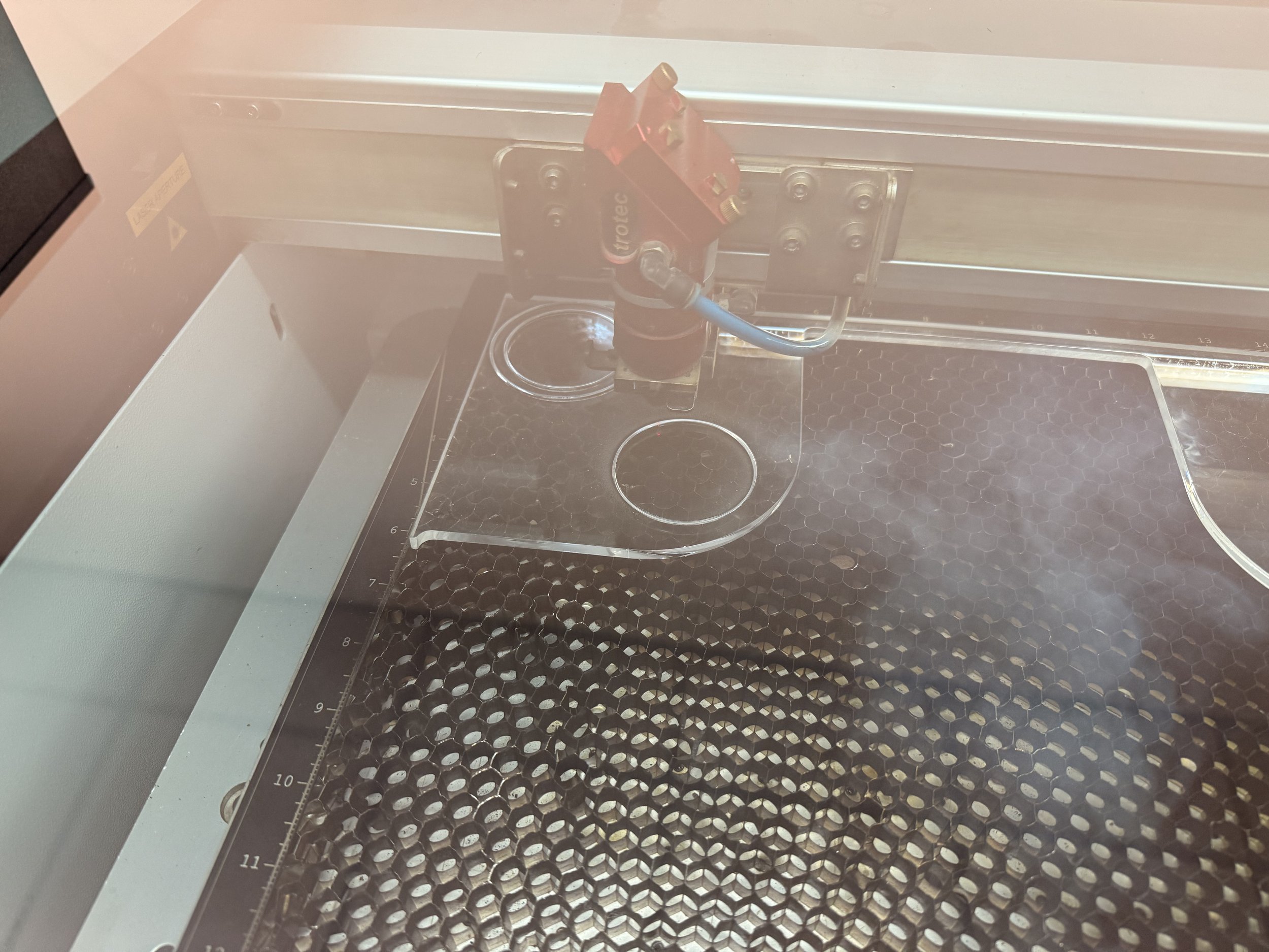
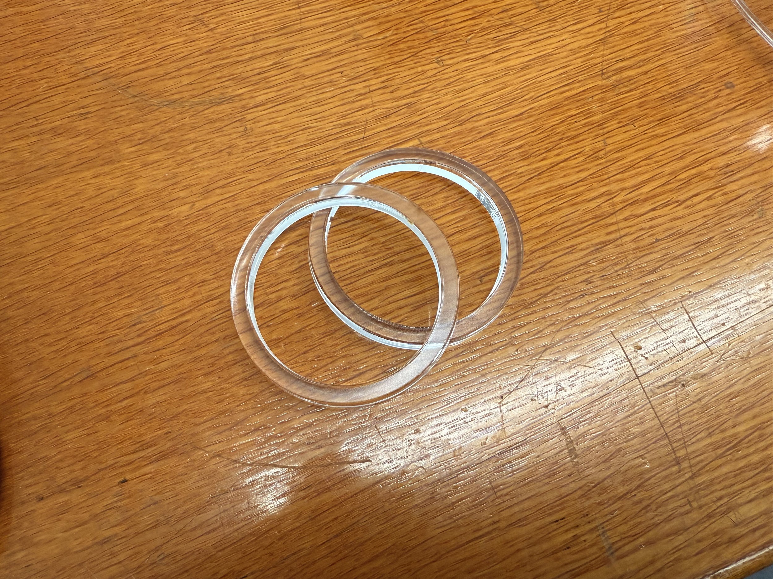
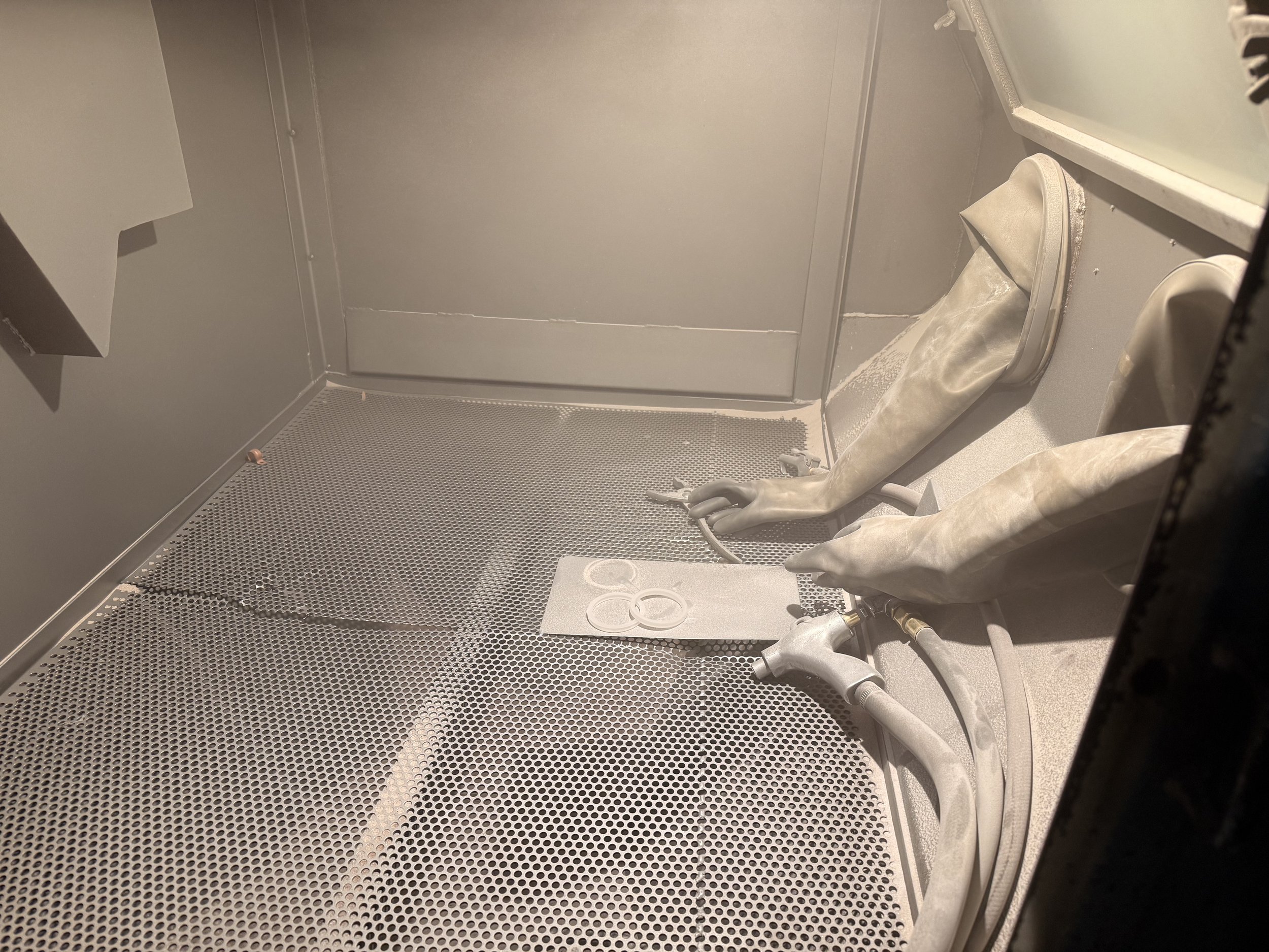
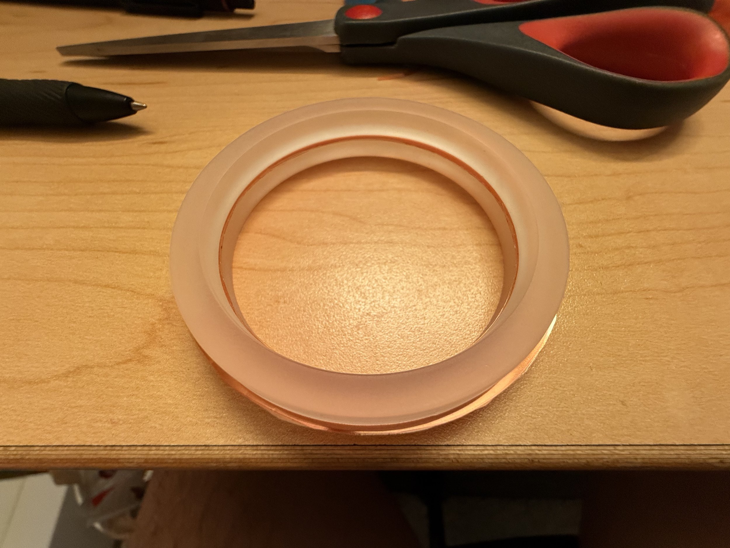
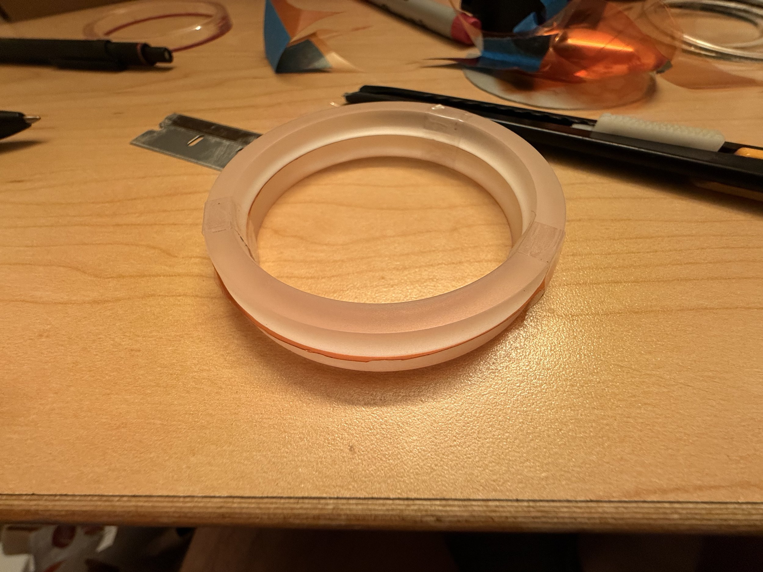
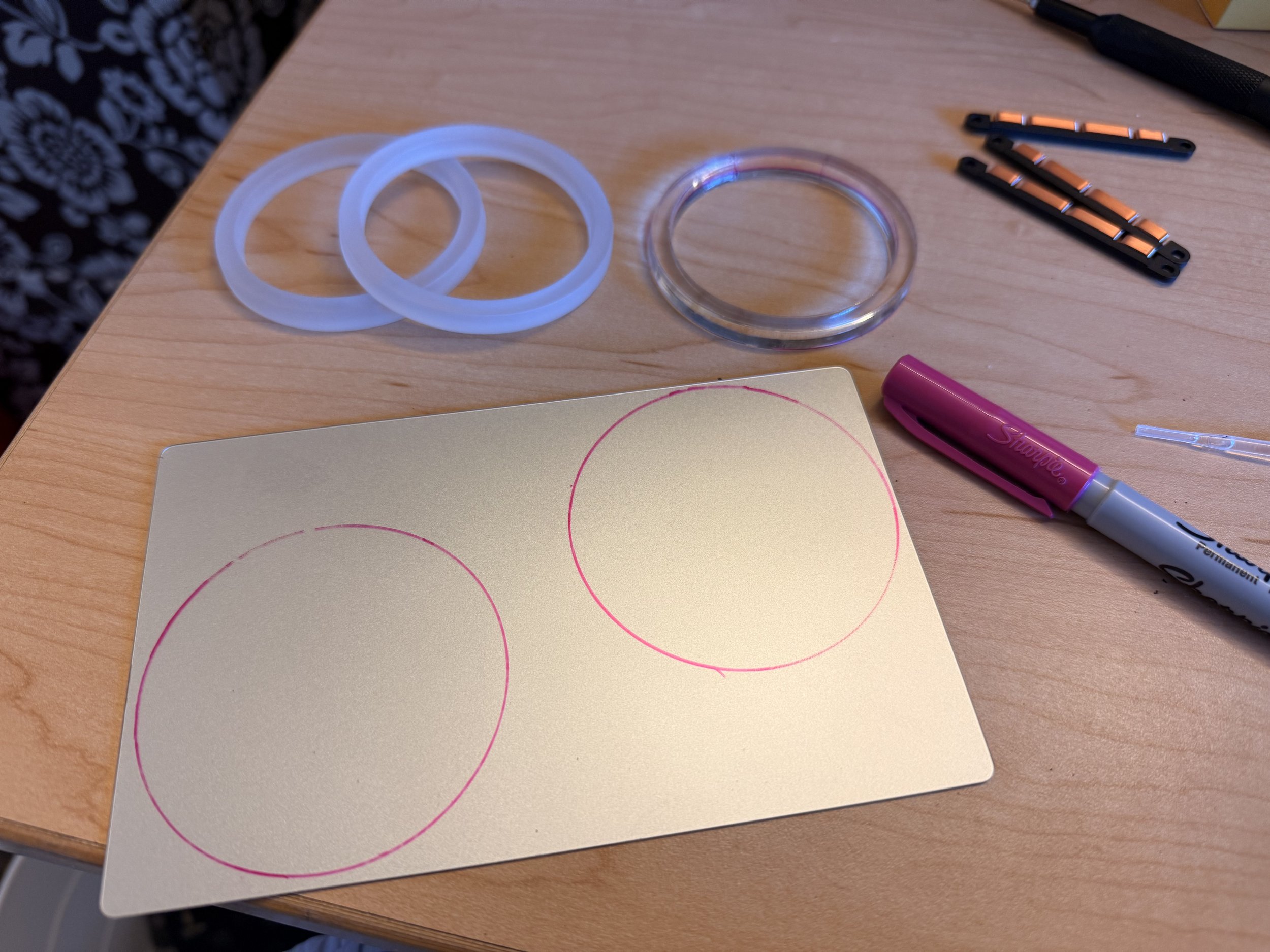
I did not want the user to see individual LEDs show up on the ring, so I anticipated ample room for diffusers. Using the laser cutter on my 1/16” frosted acrylic melted it with trial and error settings such that I didn’t have any left to try more of. I did however have some 1/4” clear acrylic that I was able to dial in without melting or burning. I gave them a bead blast shower and they diffused the LEDs perfectly.
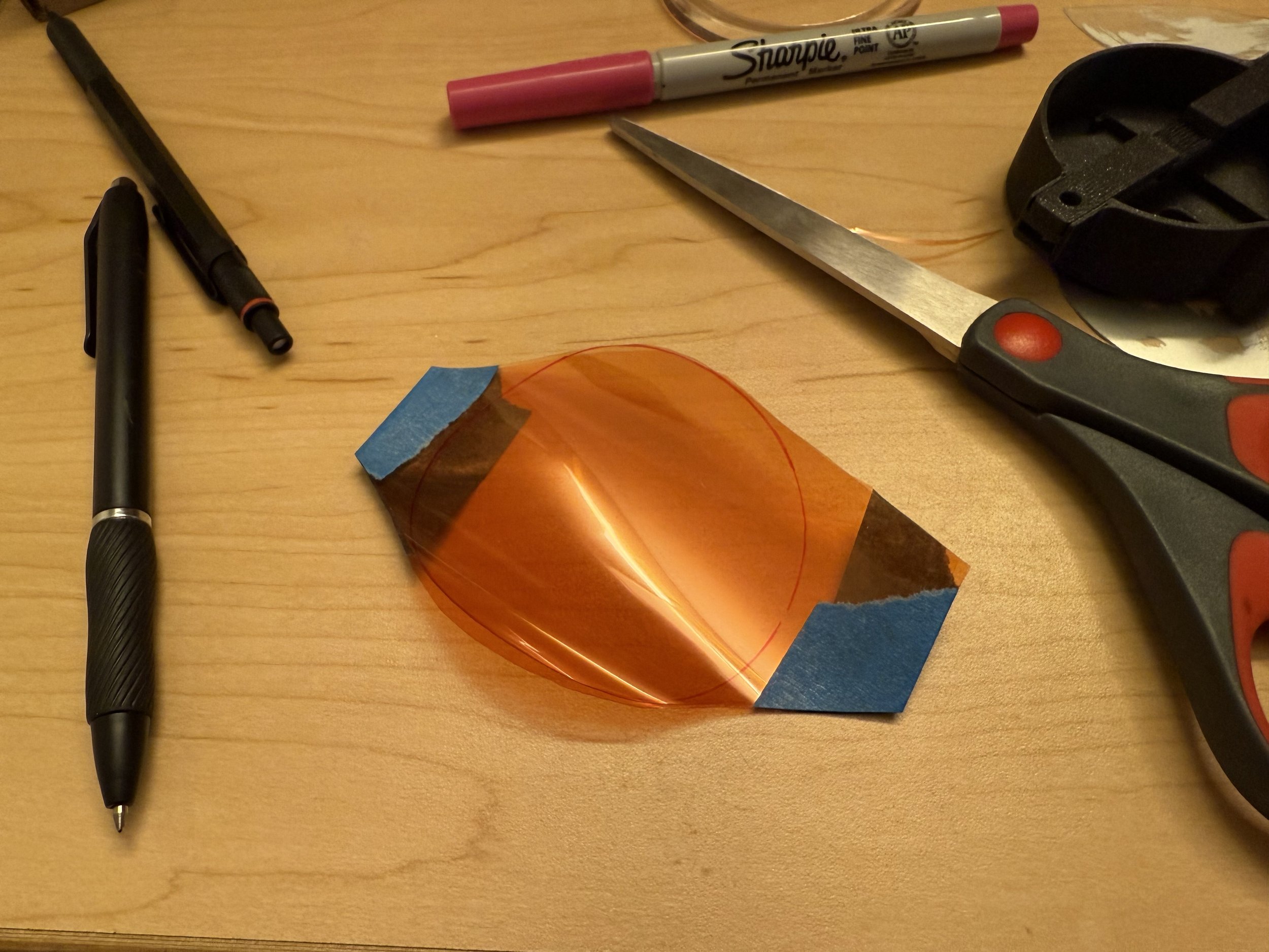
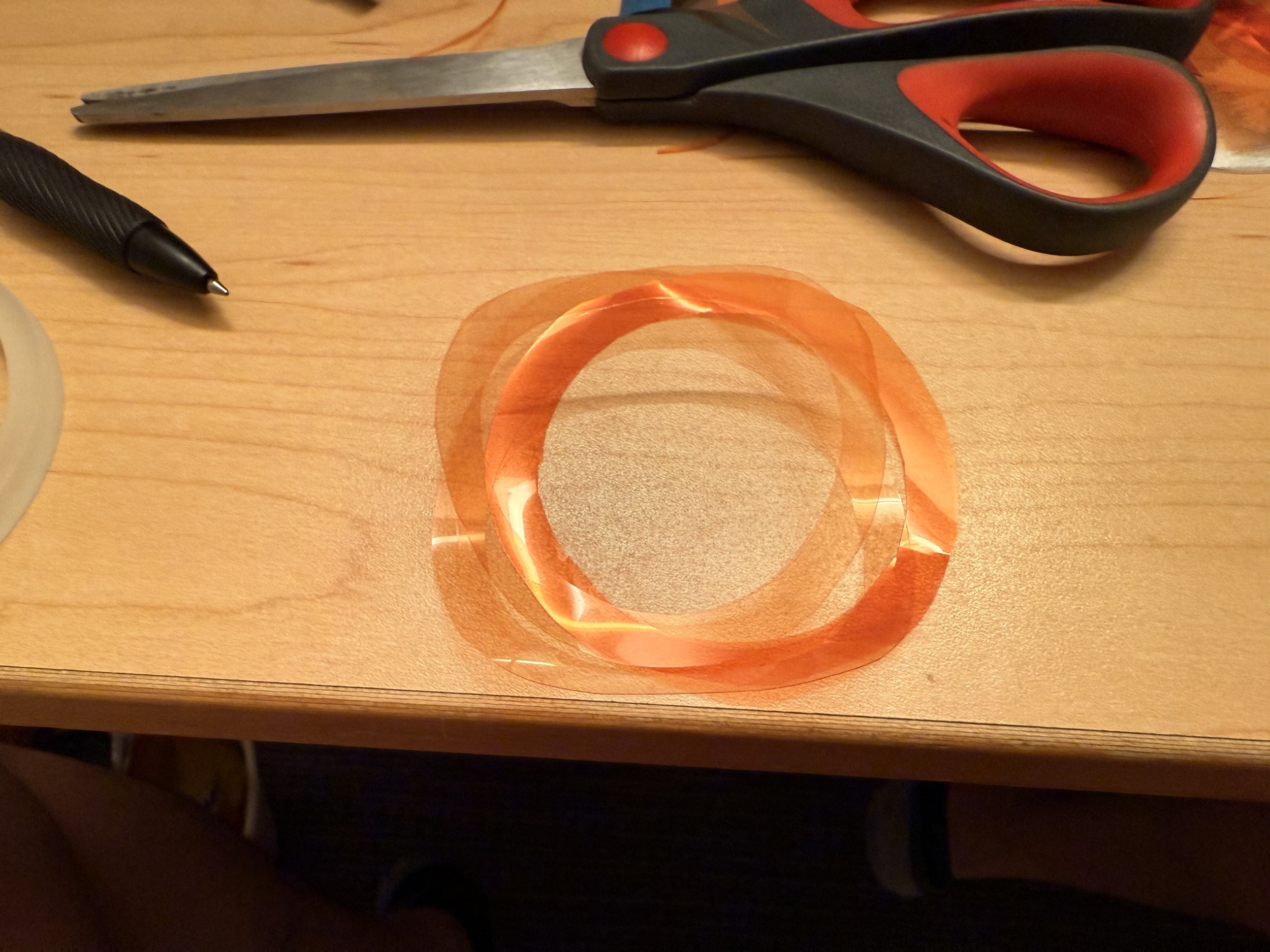
I wanted the ring light to be 2700K so I bought some CTO films to change the temperature. Again, the laser cutter melted it immediately, so I had to resort to hand cutting, which was very tricky to get a perfectly round ring as it kept slipping around. I sandwiched it in between the two acrylic rings, temporarily taped them, and tried to put it in the body, but just the slightest extra material on the edge caught onto the body and it wouldn’t fit. Deadline was approaching so I decided not to include the color filter for now.
Electronics
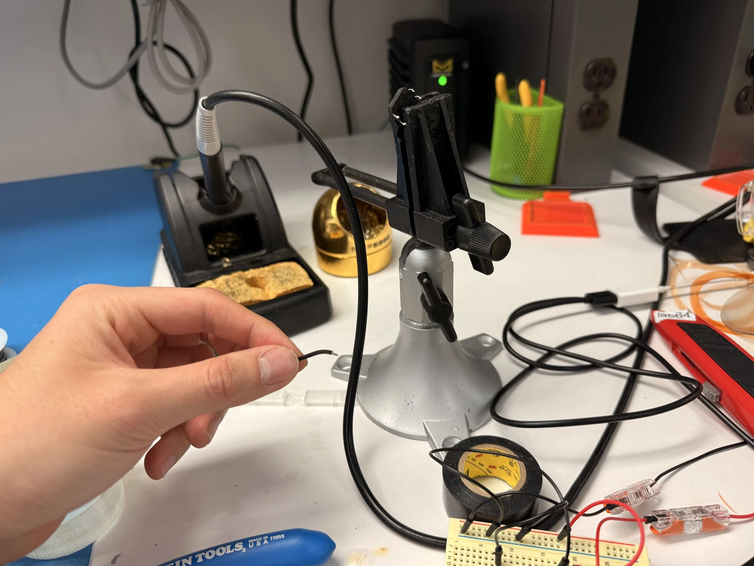
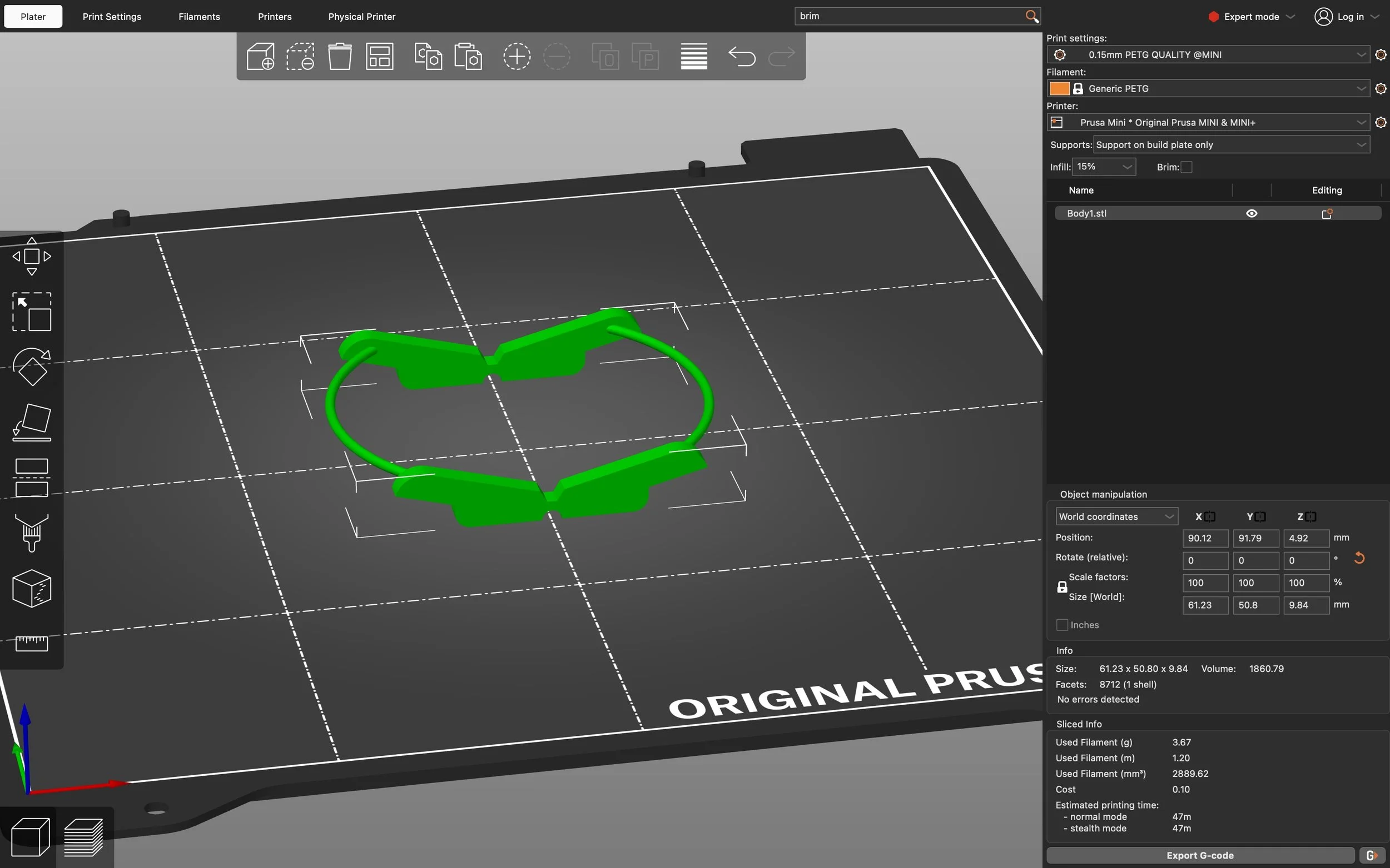
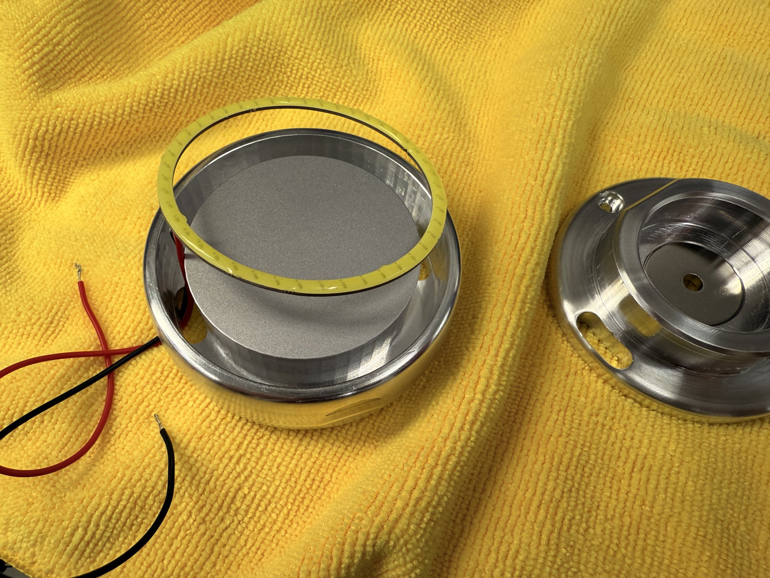
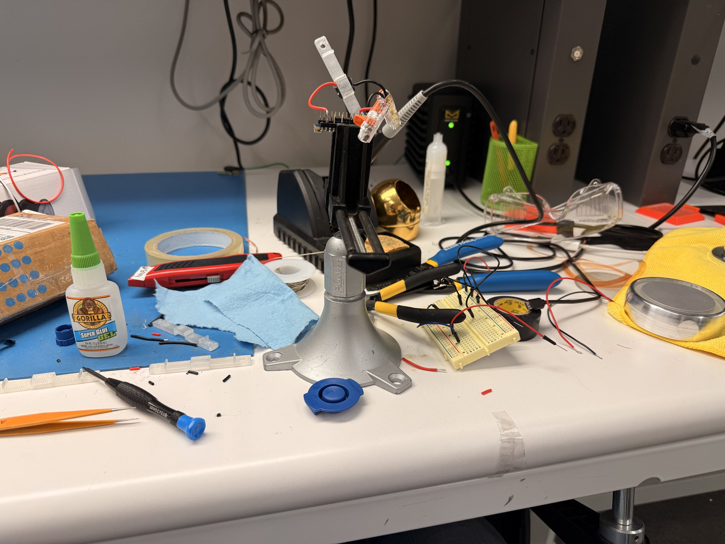
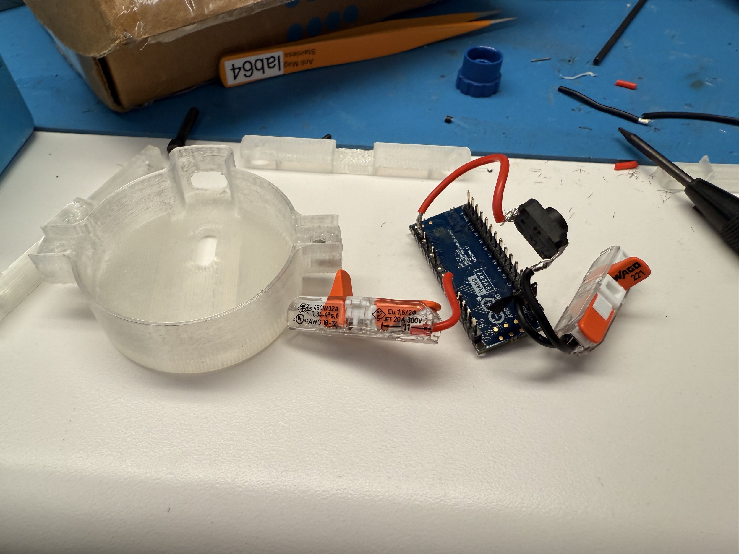
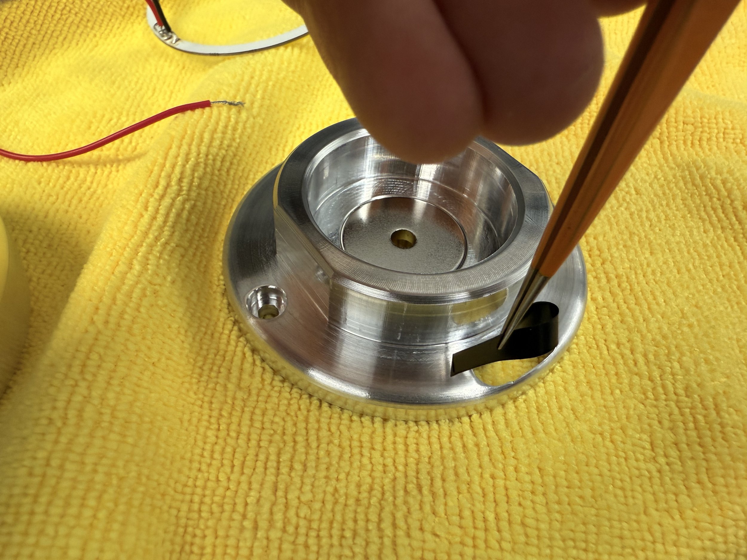
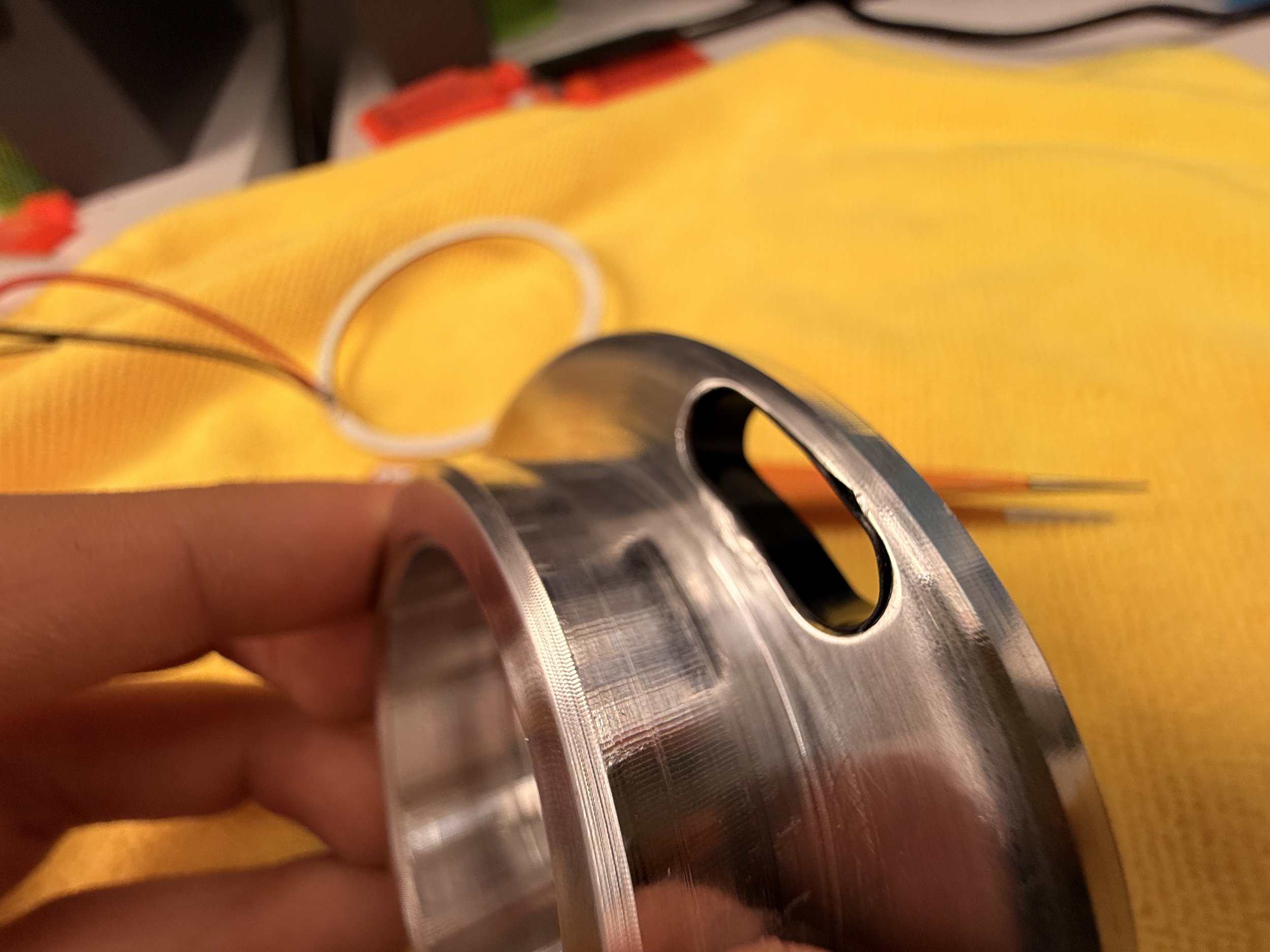
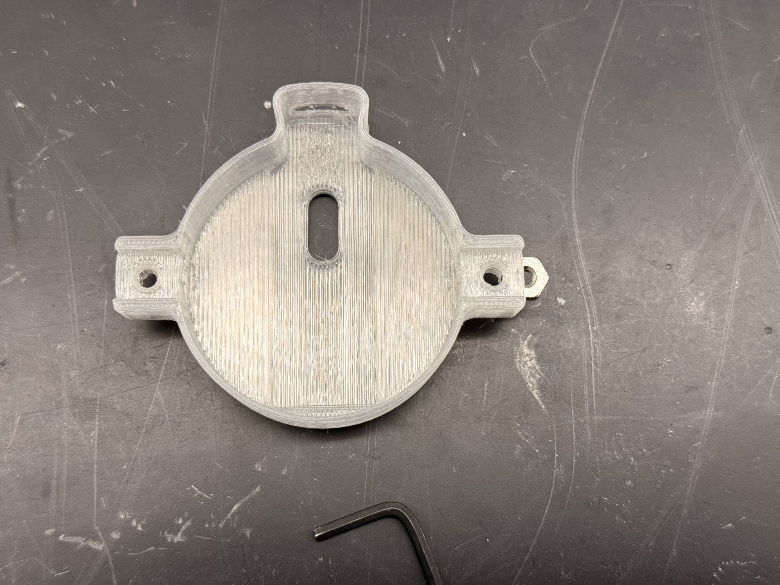
It was time to do the electronics. I have a tactile switch that the body will depress and the arduino will tun on/off the LED. I started soldering the parts together and used WAGO connectors for connections between hardware and the arduino. I also noticed two issues with the contact pads of the LED ring. 1st was that it sits on the edge so it can touch the metal body and short it. I decided to add electrical tape to the wire tunnel of the body. 2nd was that because it was sitting against the body, I had to re-solder the wires so they pointed up. I also printed a housing to stuff all the electronics inside.
*again, I am not an electrical engineering professional
Glass terror
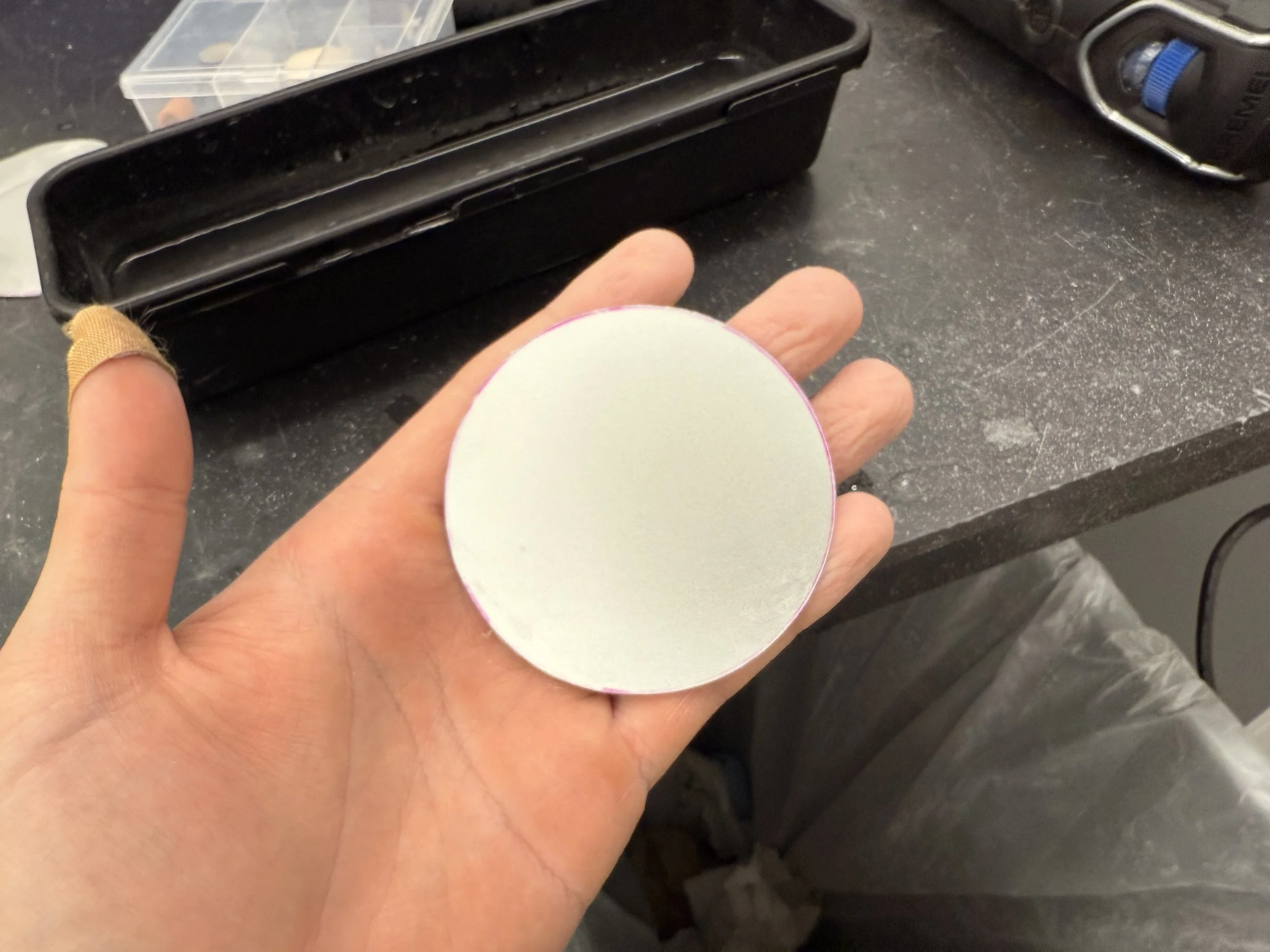
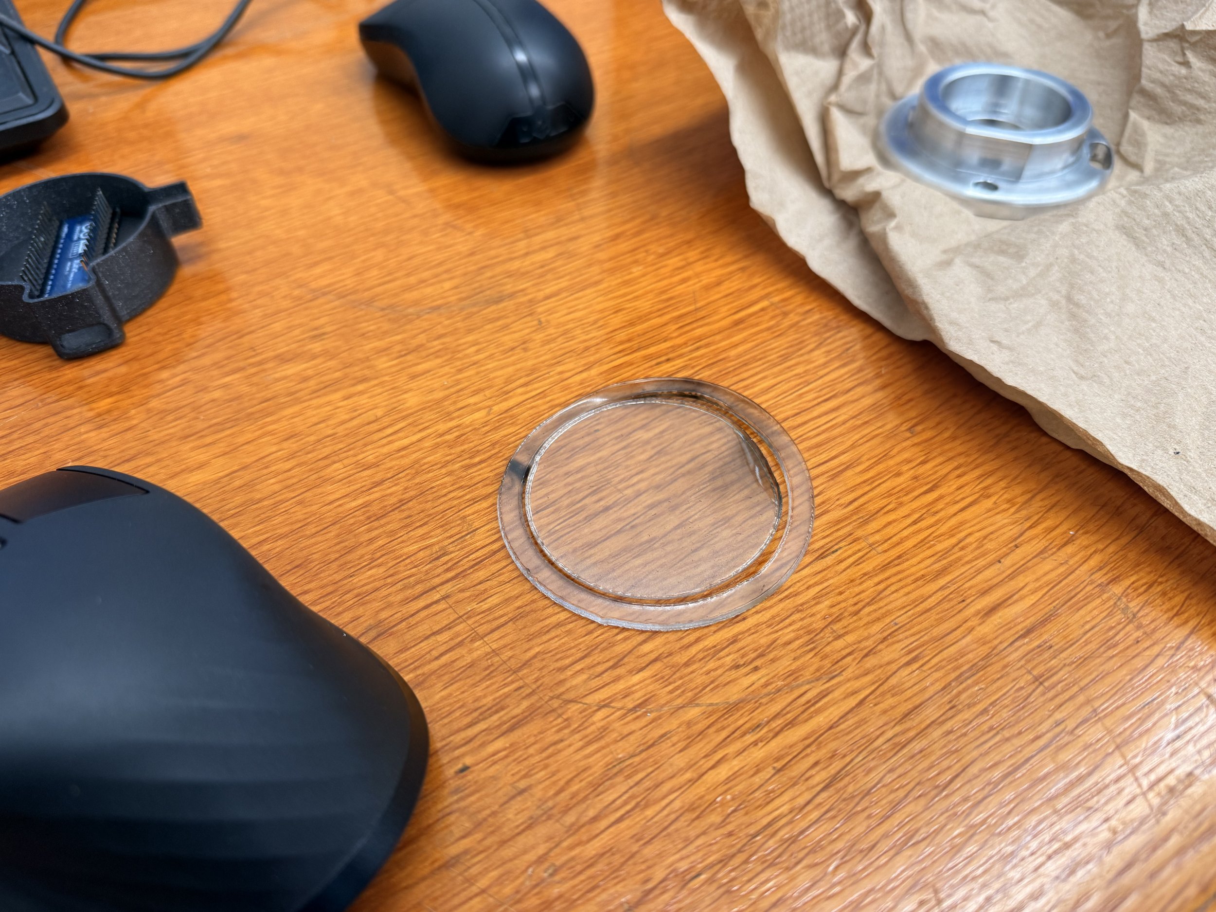
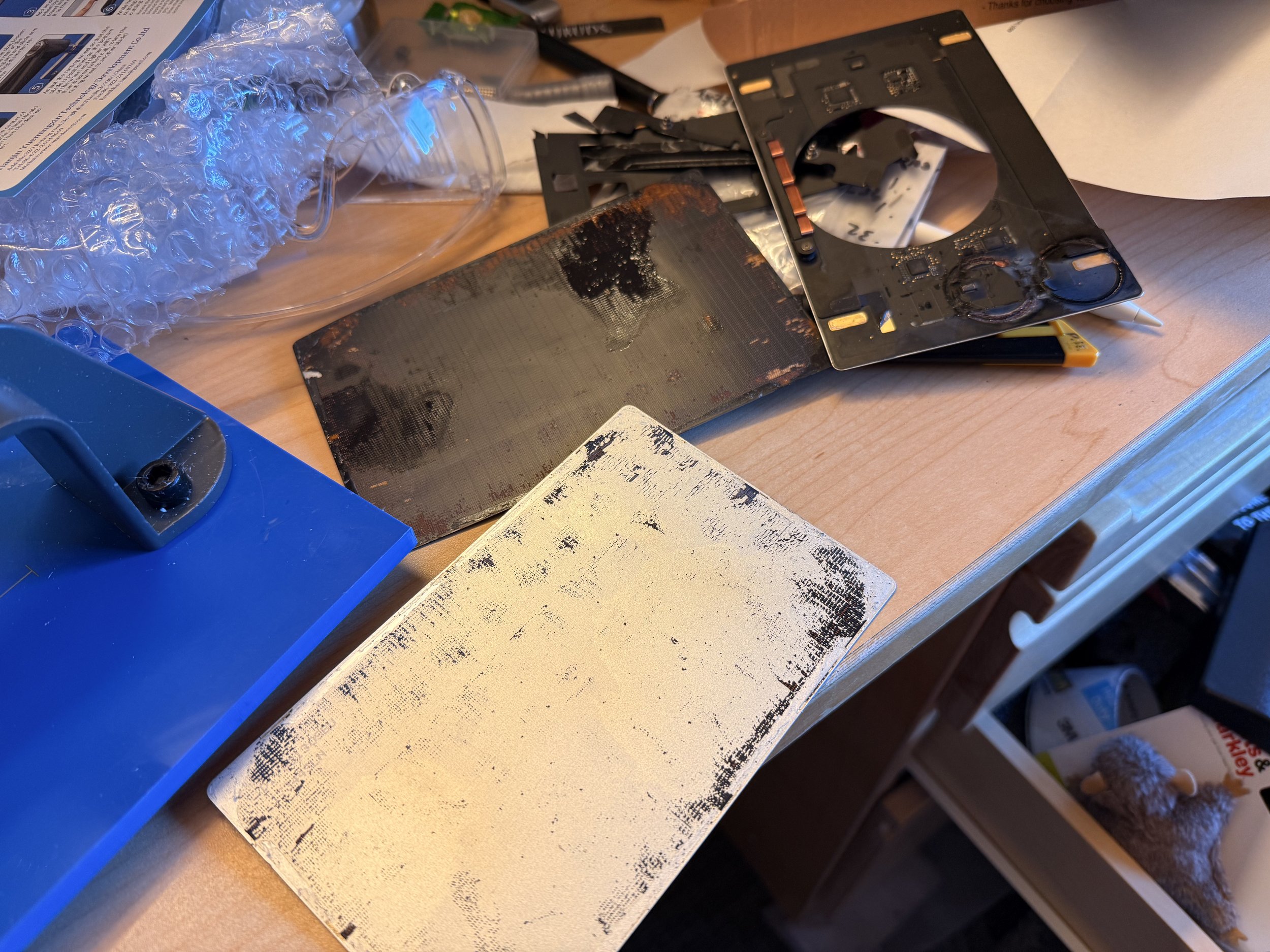
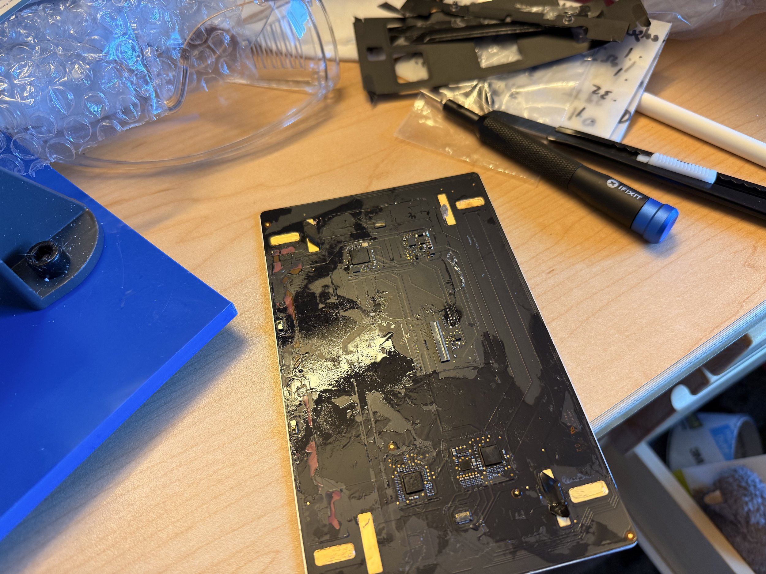
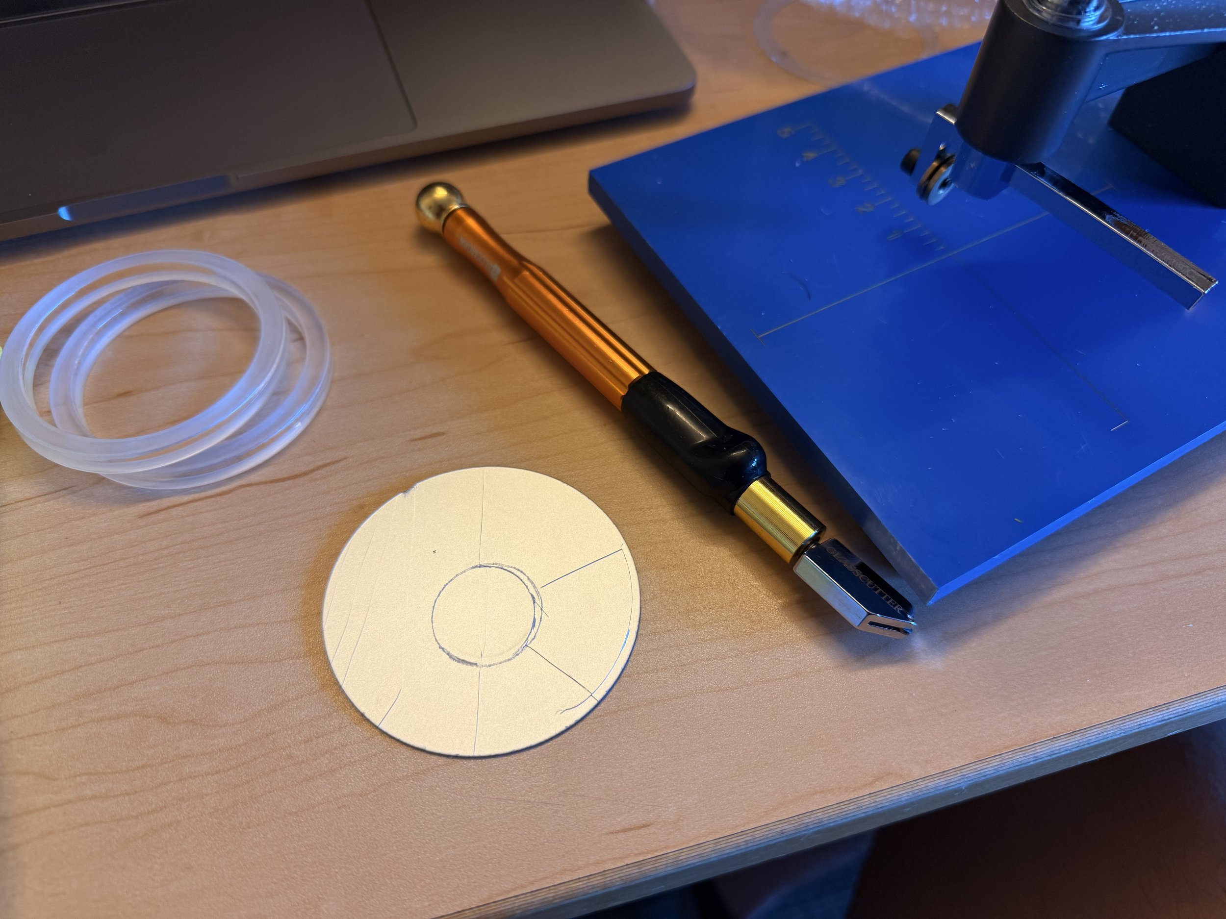
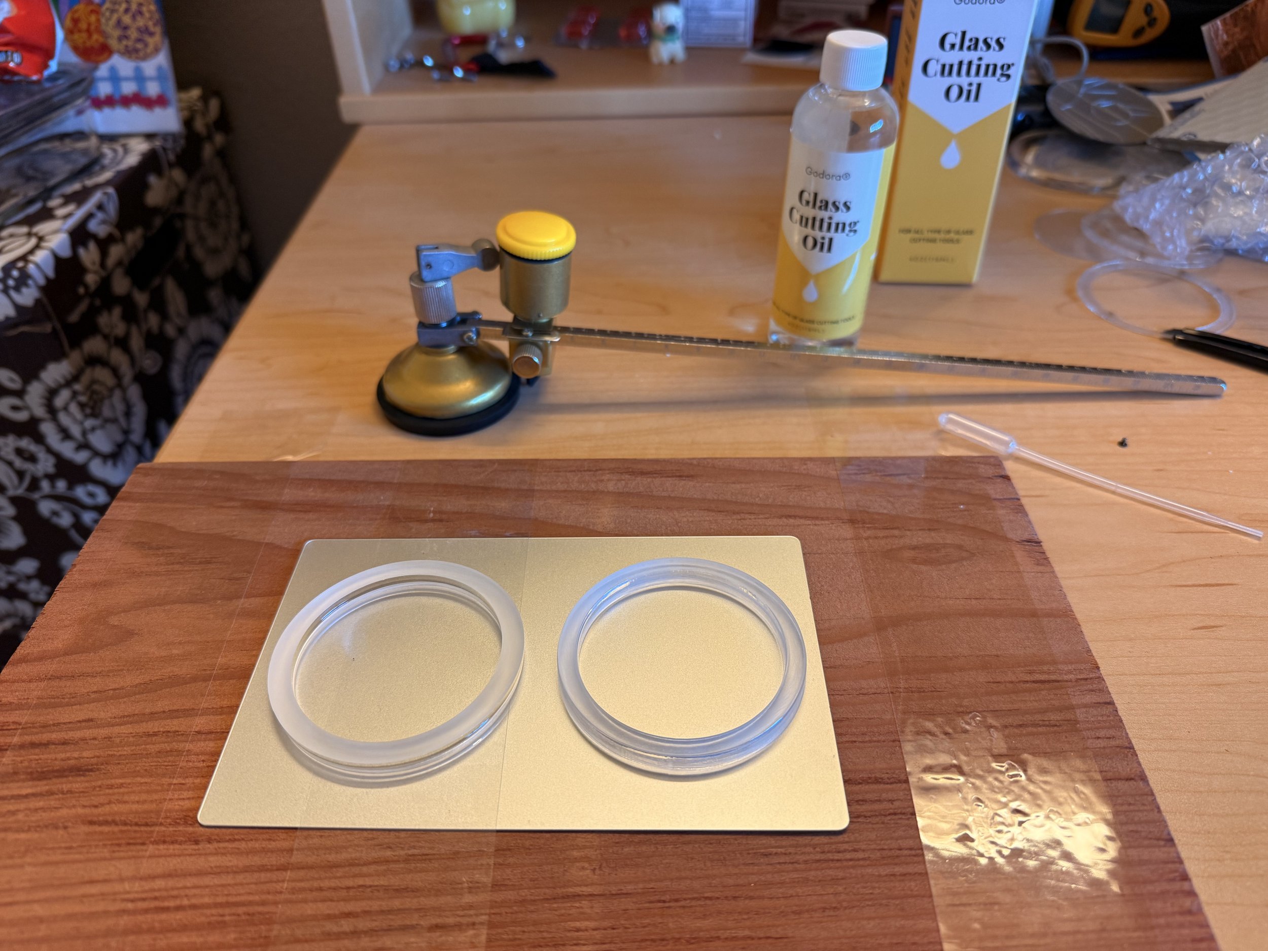
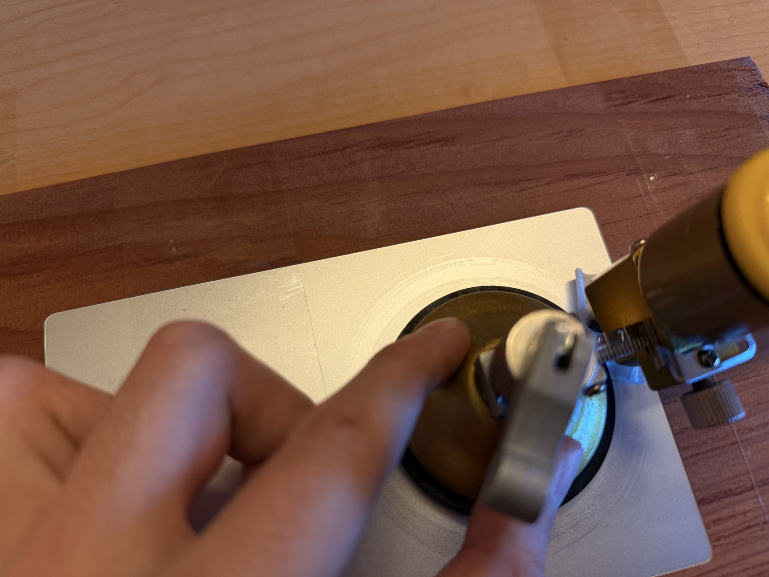
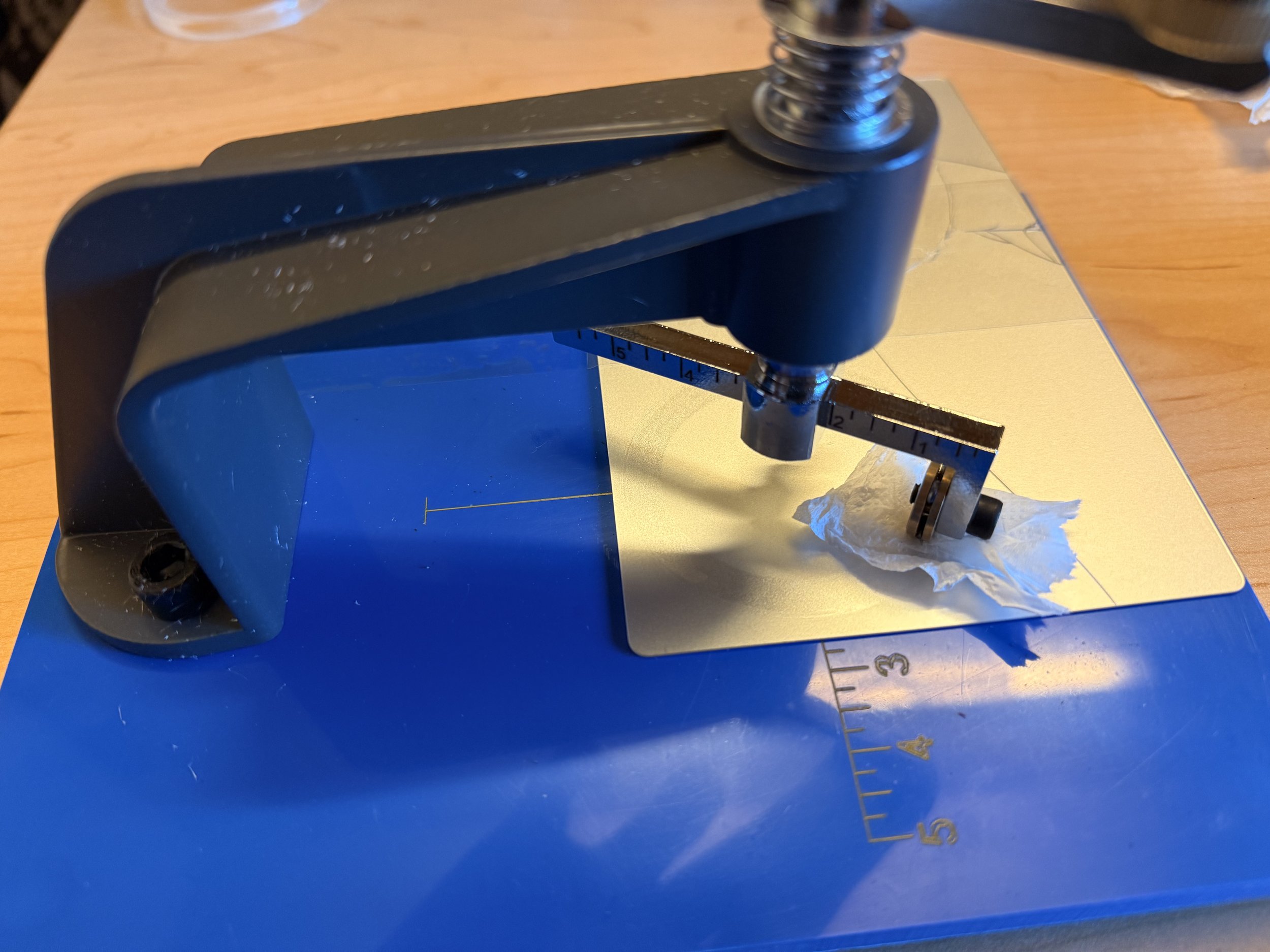
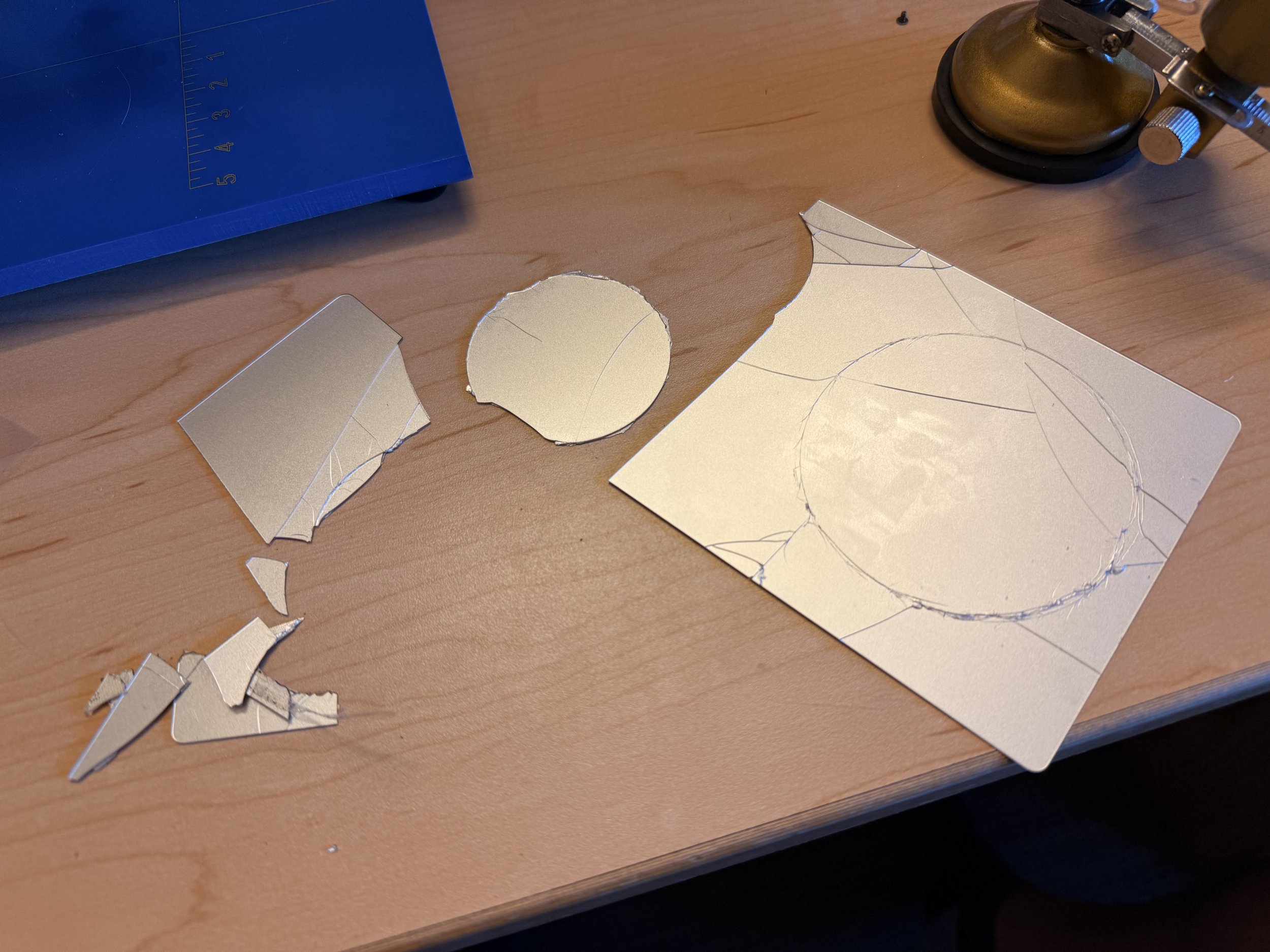
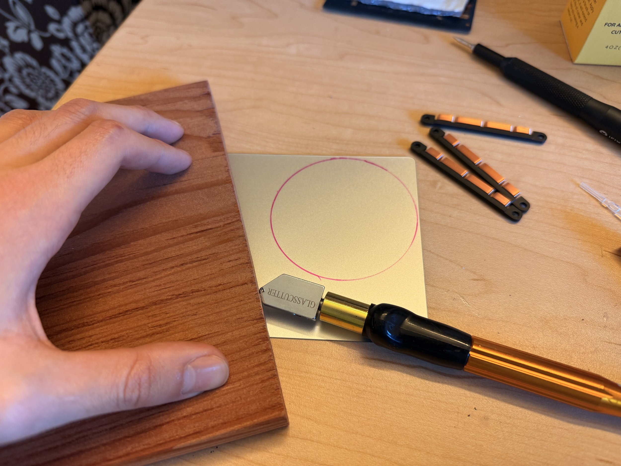
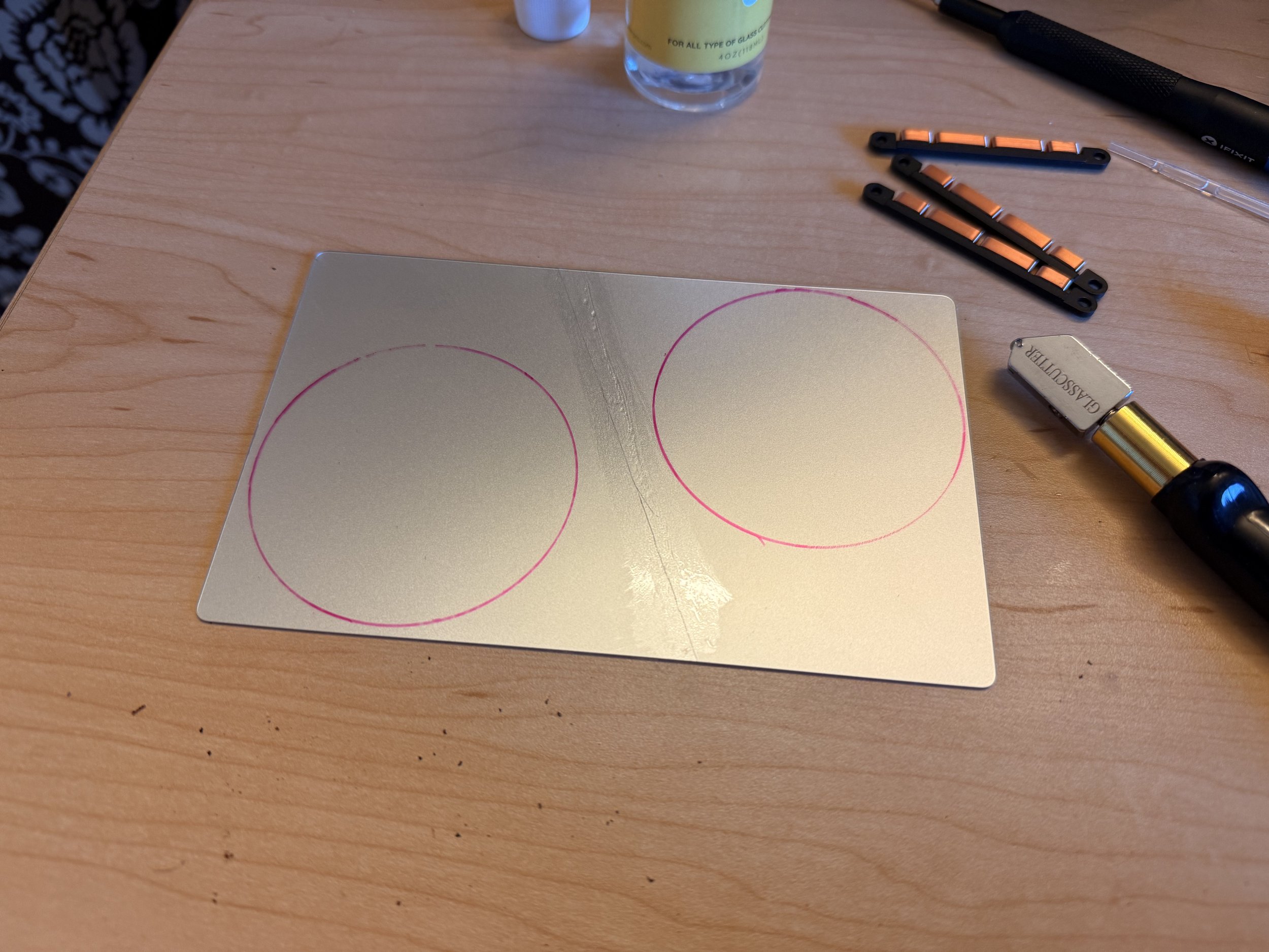
I got more replacement trackpads and it will time to start testing them again. I had to remove the haptic mechanism and It took quite a bit of time to remove the perimeter brace, so the glass back would lay flat. I bought two circular glass cutters, glass cutting oil, and watched numerous instructional glass cutting videos online. I ran some test cuts on my broken glass pieces first, but I wasn’t sure if the existing cracks were causing additional cracks to form.
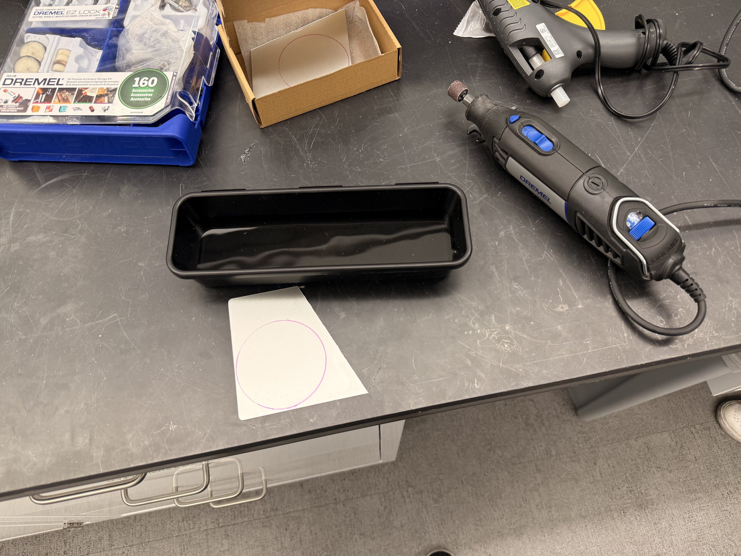
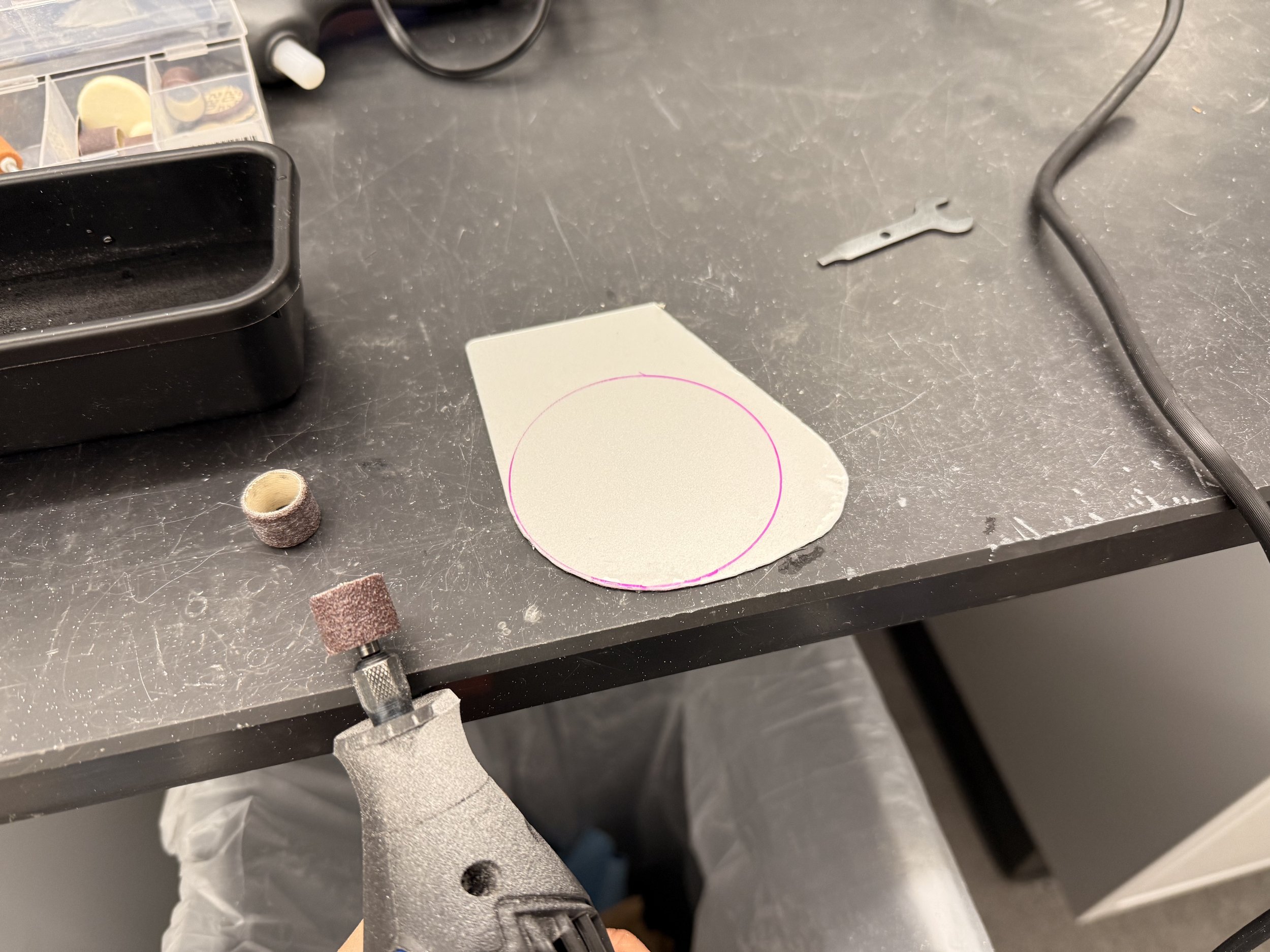
I decided to just go for it and cut to size; each trackpad has enough room for two trials. Unfortunately, the glass still decided to crack for both glass cutters. I decided it wasn’t worth pursuing this path, so I went the old fashion way and sanding glass. I went to lab and dremeled the glass piece making sure to dip it in water to lubricate and cool it every so often.
I would change the sanding drum as it runs out, but I would have to be careful initially since the grit is very course. If I’m too greedy, it can knick the glass aggressively and cause a crack. It happened numerous time and some were too close for comfort. One of them formed but swerved away. A second one shot straight to the edge of the circle. I tried saving it but reducing the length of the crack, but it grew as much as I reduced, so that was a fail.
I had to start over, but this time, I used the straight glass cutter to remove more of the surrounding material to save a lot of sanding time. Initially, i was afraid cracks would propagate if I got too close to the circle. After 9 hours of sanding, I legitimately developed carpal tunnel that night, but finally achieved my circular piece of glass.
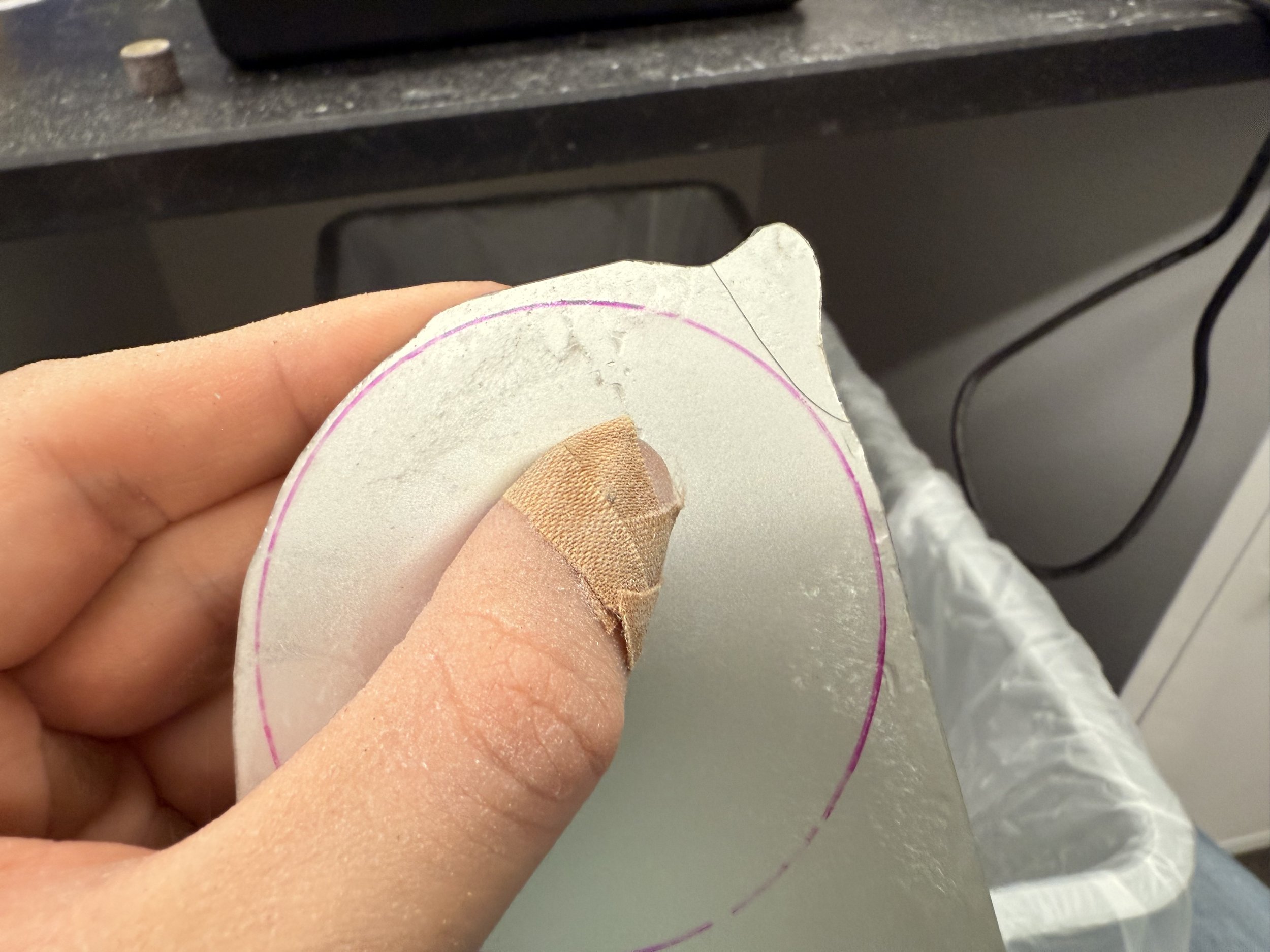
The crack
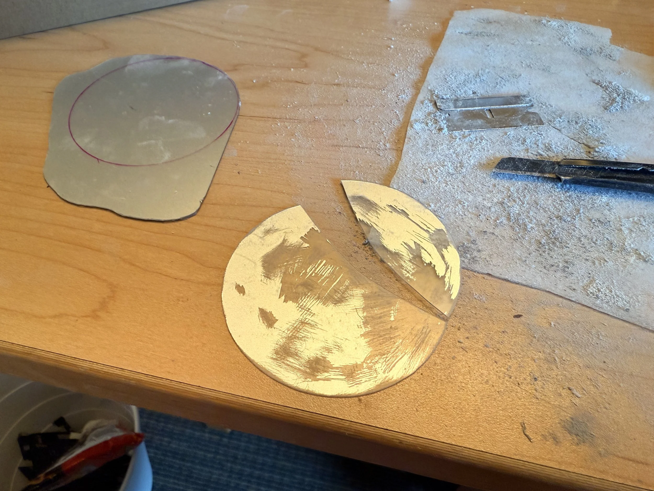
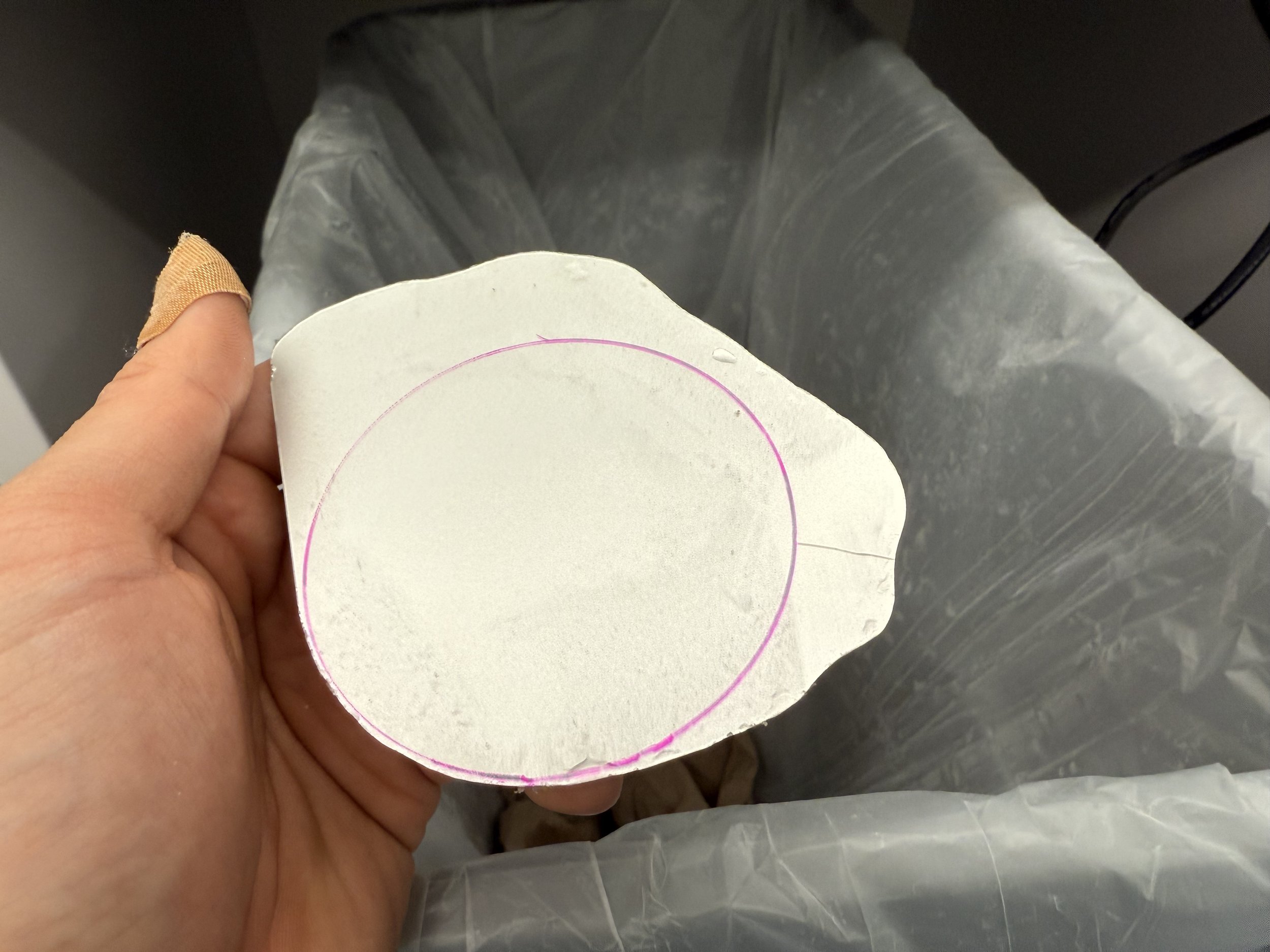
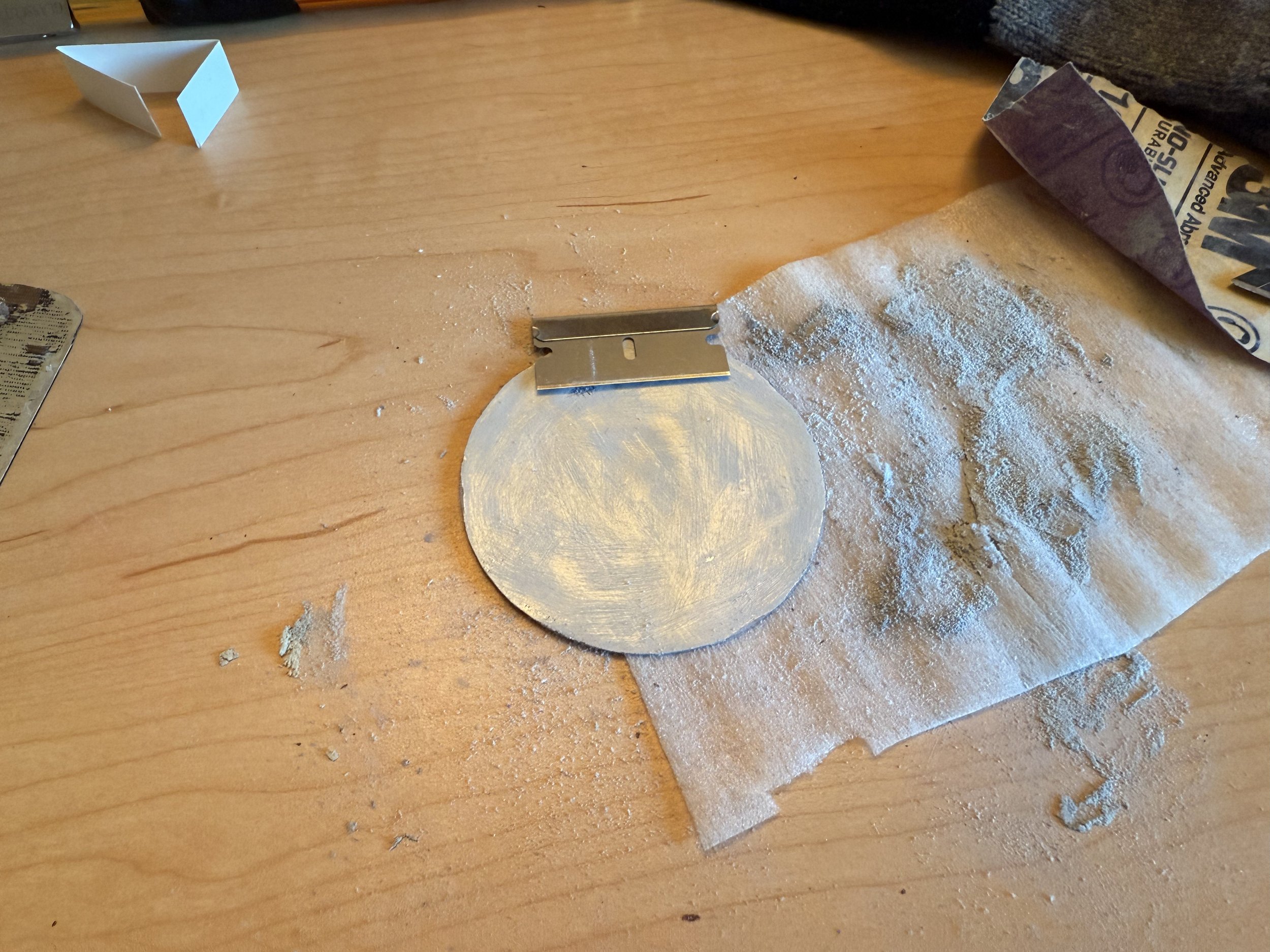
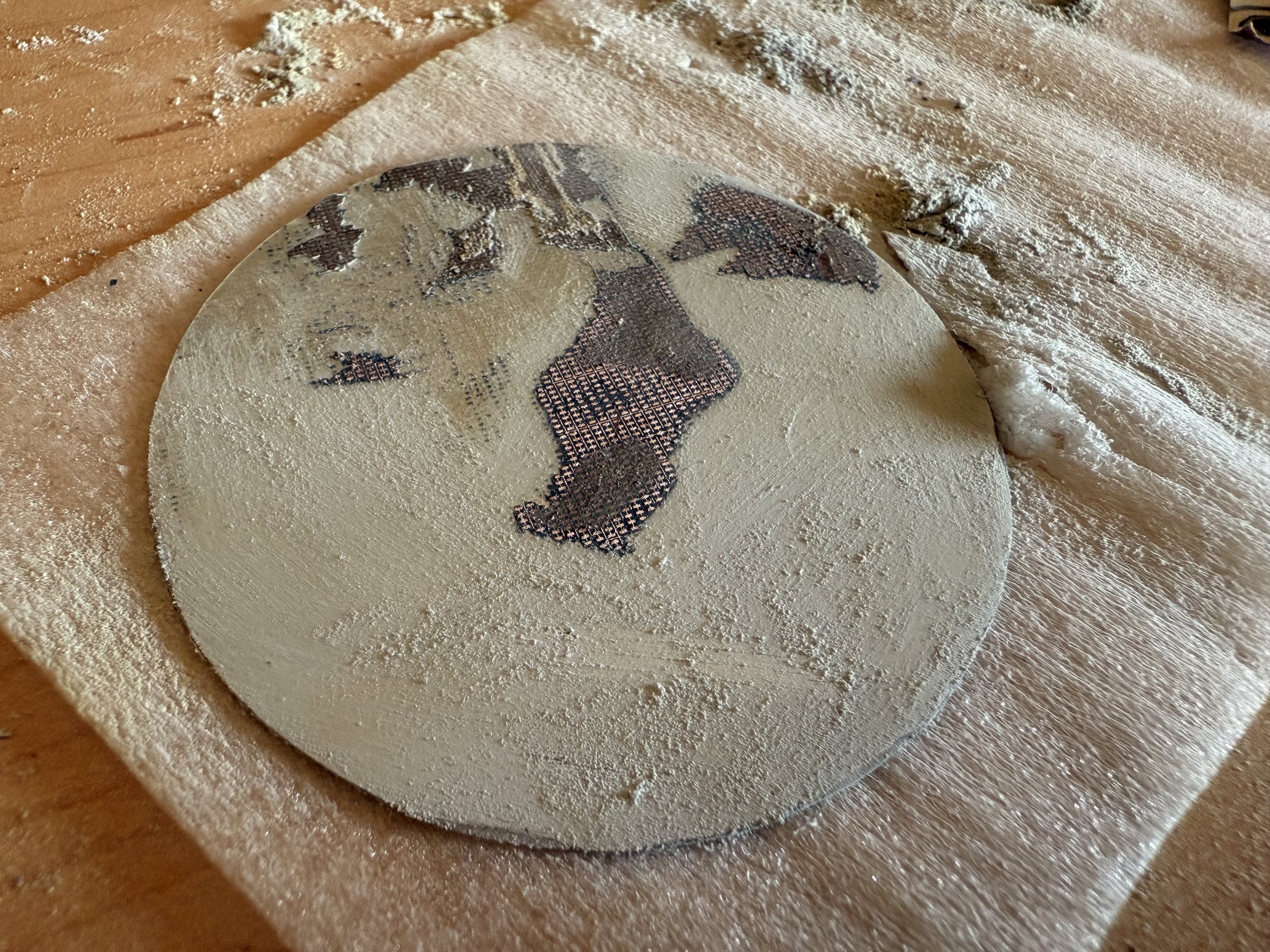
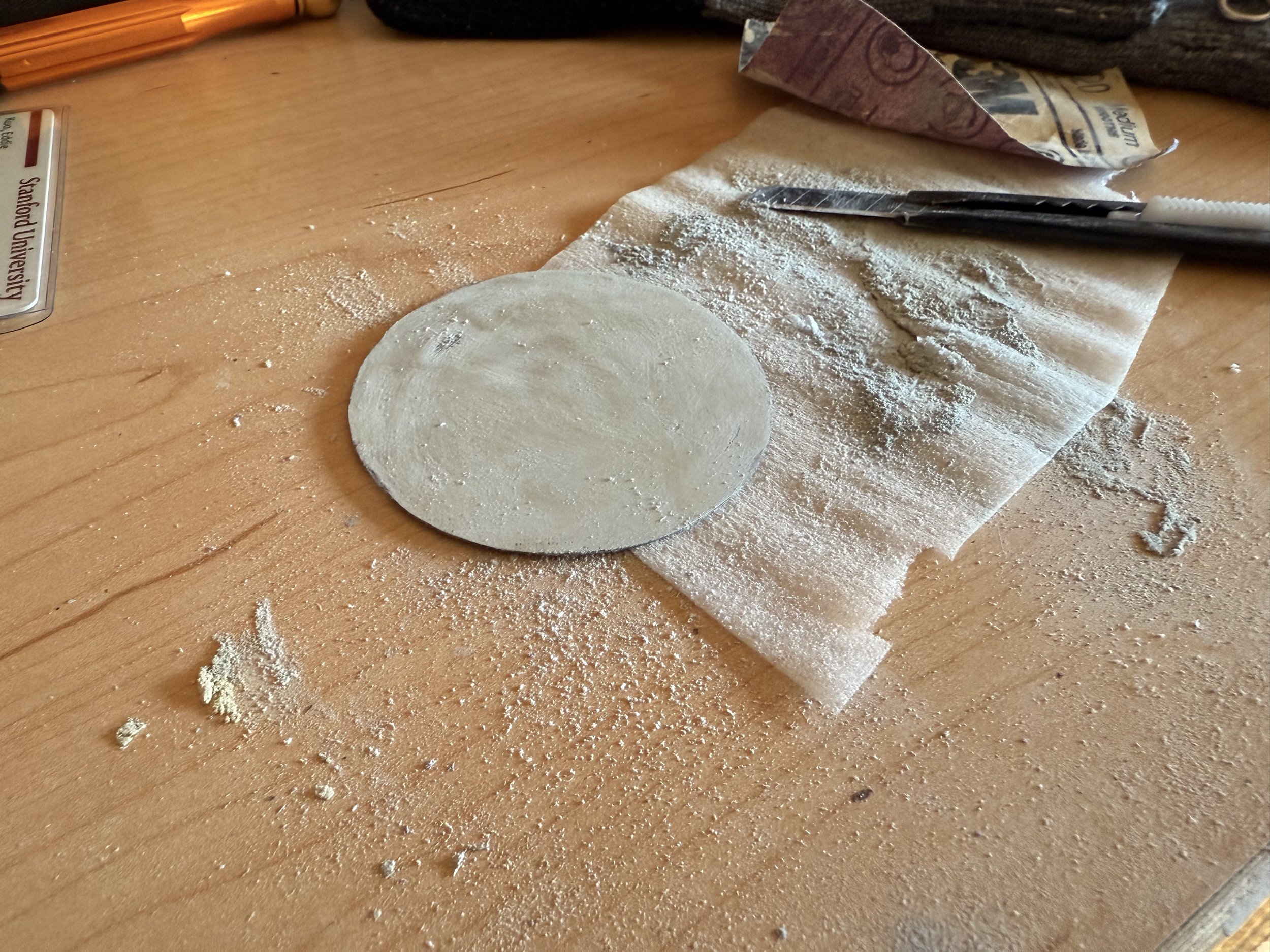
Now that I got my circle, I had to remove the painted layer on the back of the glass to allow the aluminum texture as well as the light to show through. There is this very hard gray layer above the paint, which I suspect is some sort of adhesive that holds onto the bracing layer; it also didn’t help that there was some leftover of that bracing layer. It was very hard to remove and does not chip away like the paint does. I used a combination of sanding and chipping.
Out of the blue, as I was chipping the glass decided to crack. There was nothing I can do as I did not have enough time to sand a new one. I went ahead and portrayed my button without the cover glass for now. But the good thing is that the sandpaper caused scratches that wouldn’t have looked good anyways.
Display mount, remedy & assembly
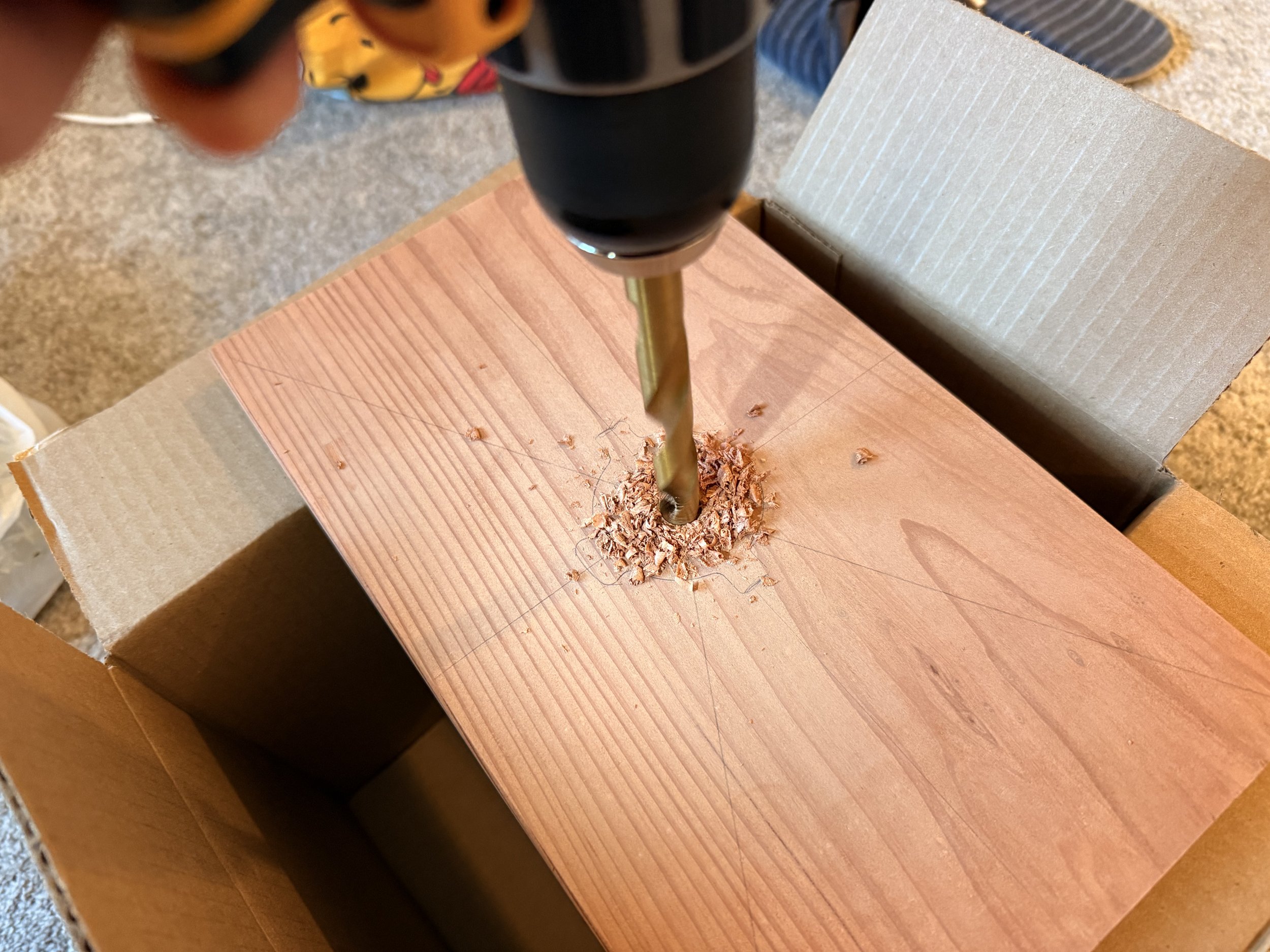
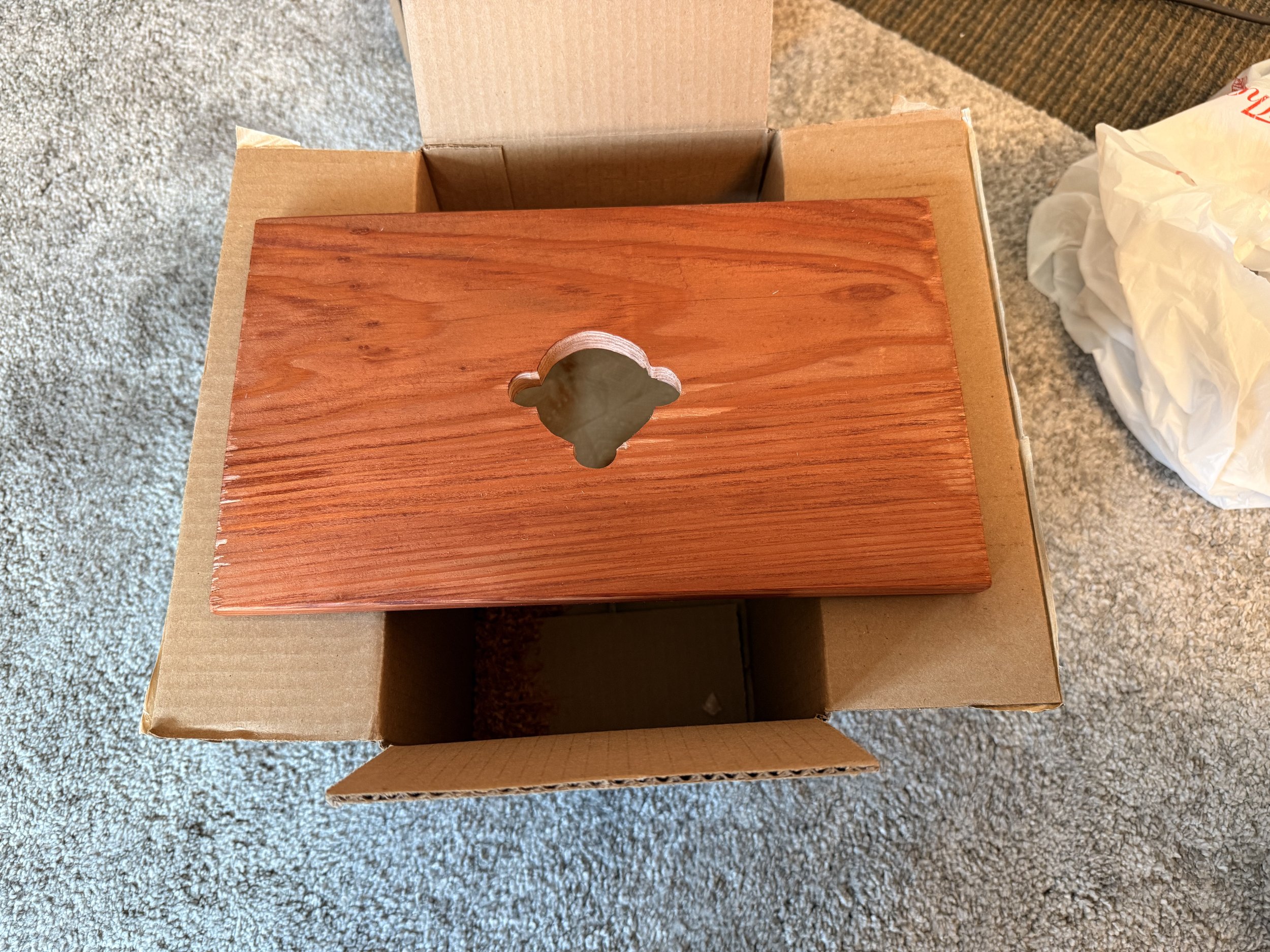
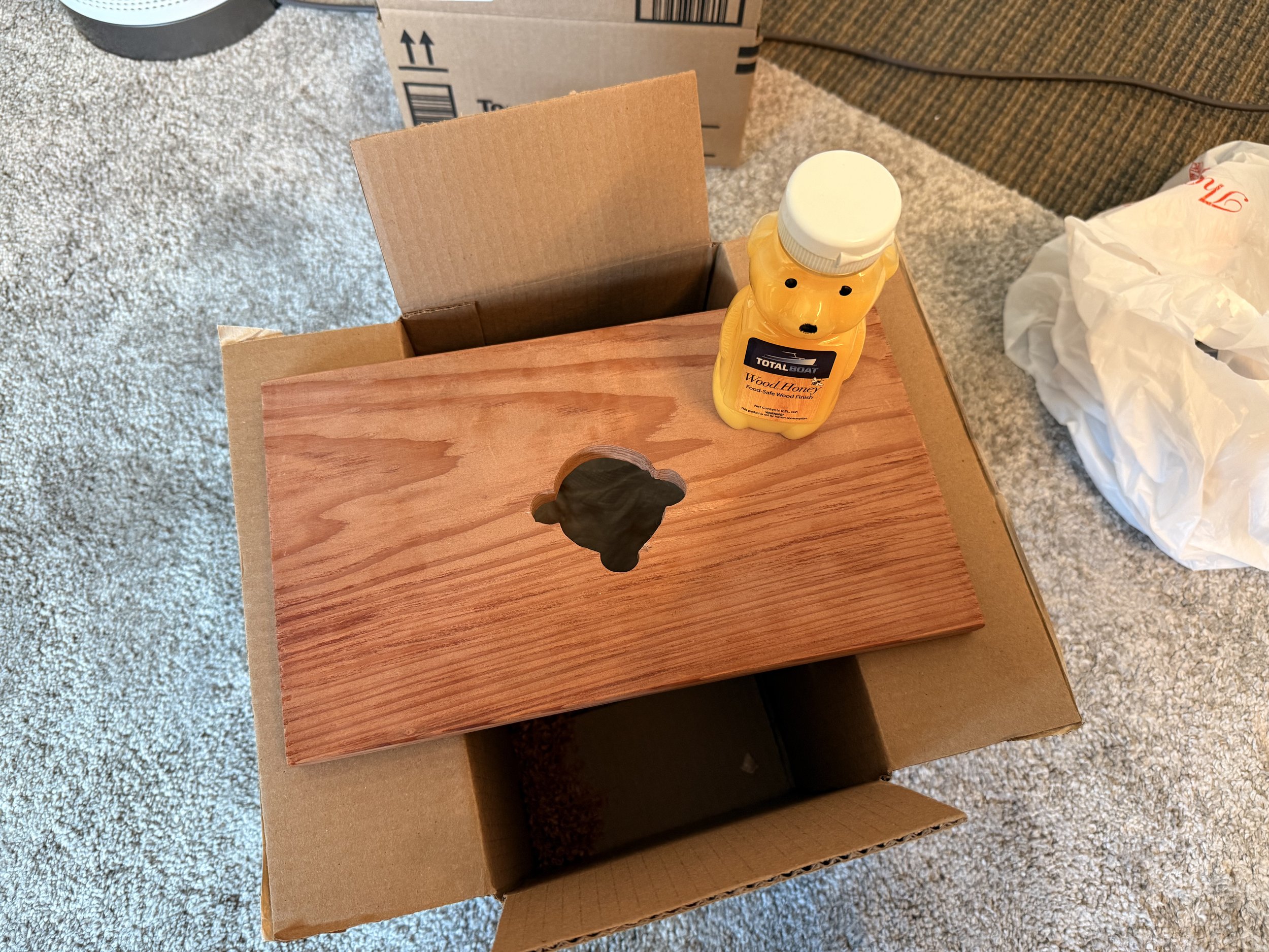
Because I had an electronic housing to hide, I thought it would look best if there was some sort of display mount to put the button on. Besides, it’s supposed to mount onto the wall, so I thought my extra piece of redwood plank would do just that. I treated it with wood honey to give it a deep rich warm tone.
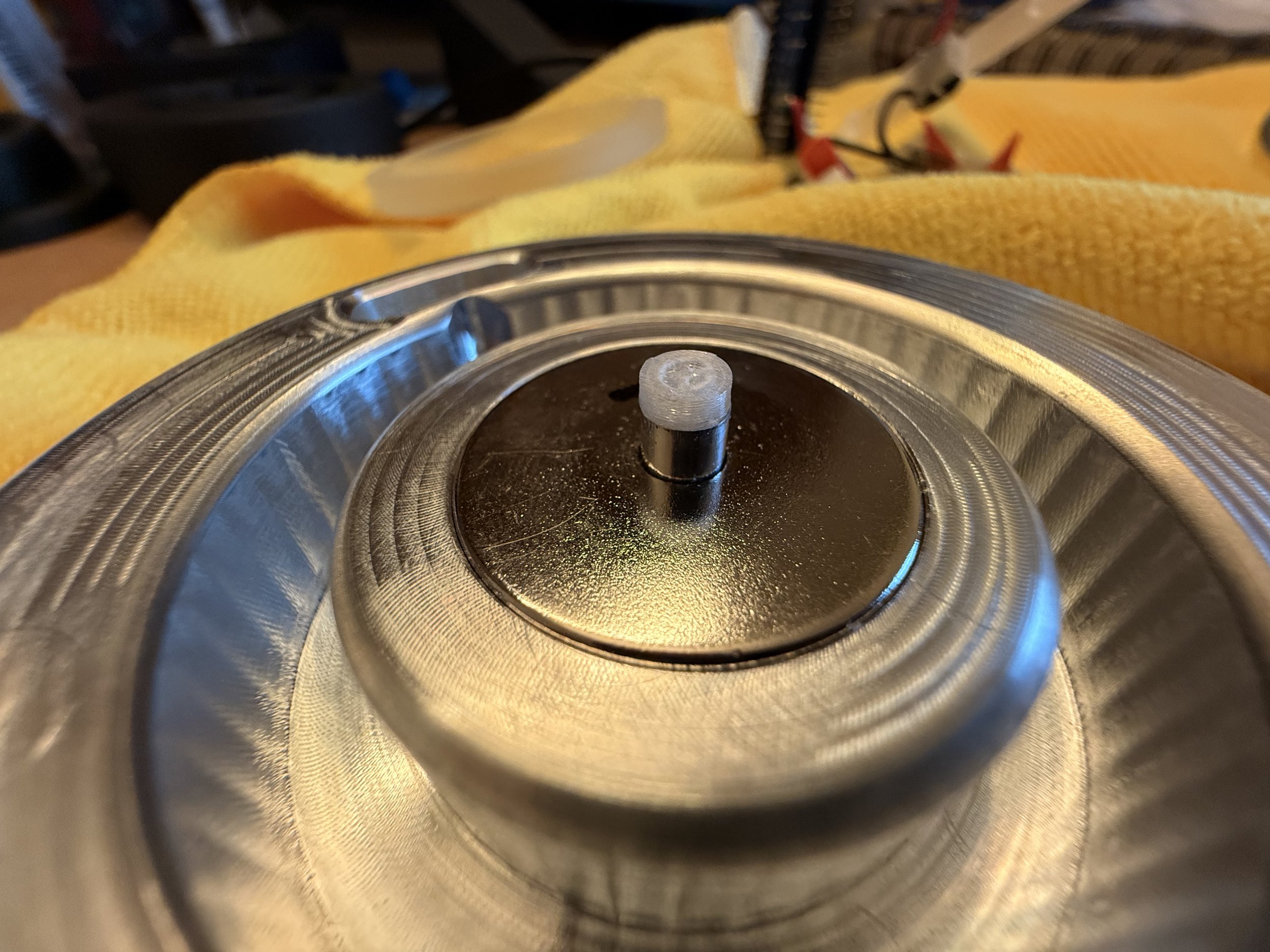
Due to the nature of the magnets, an extra piece had to be added onto the depressor to reach the button.
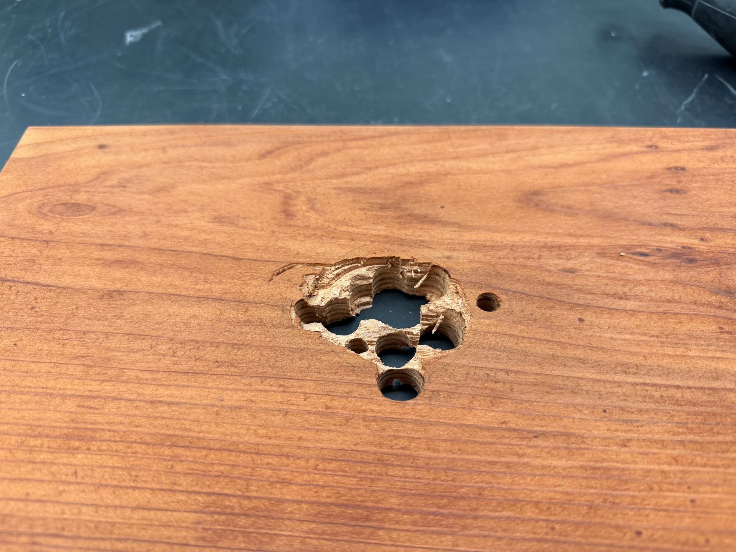
I made the markings, drilled, and dremeled out the cavity for the housing. The wall plate will fasten to the housing, the body will magnetically attach to the wall plate, and a wire will run out of the housing to my laptop to power the electronics.
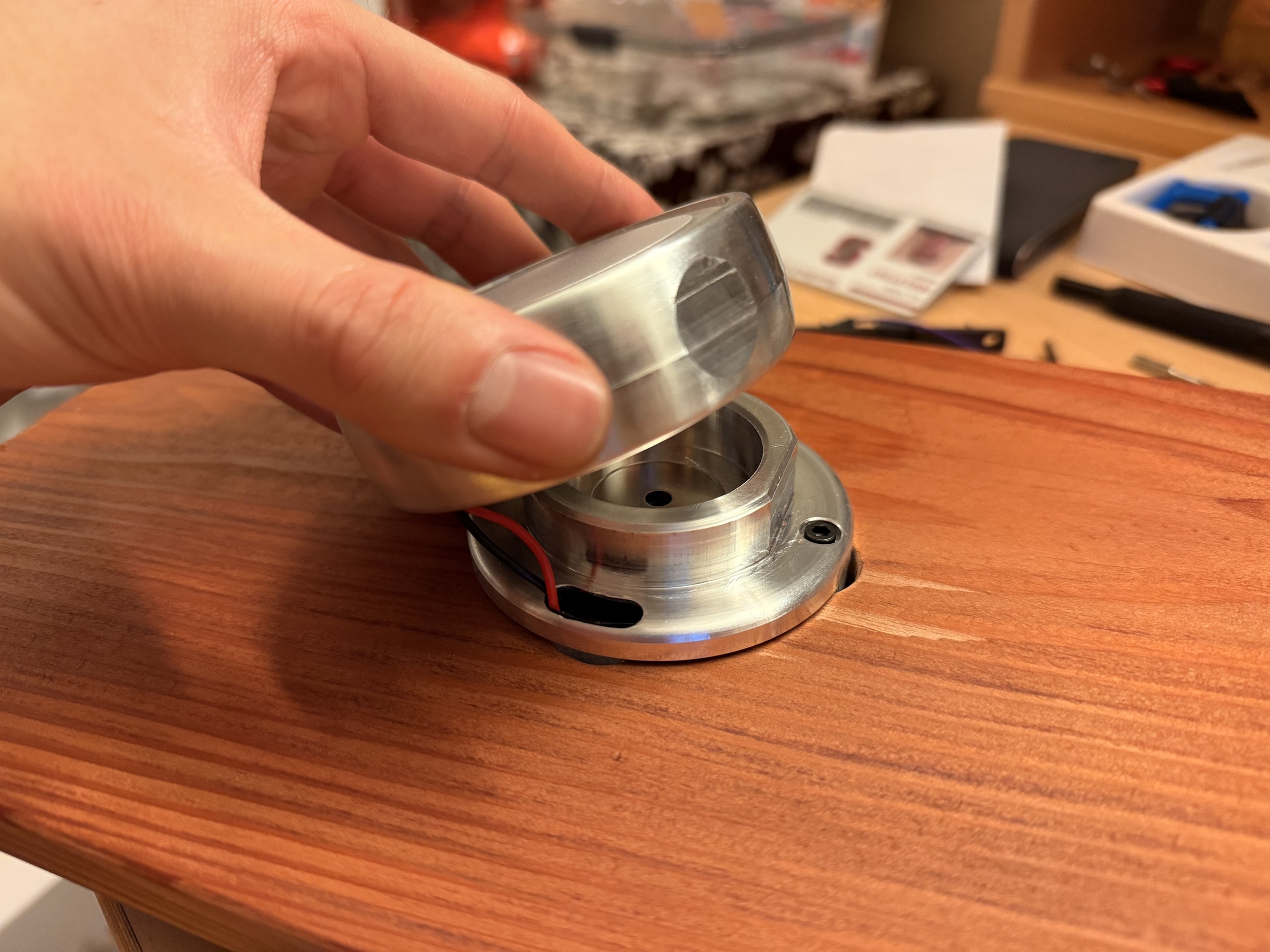
i underestimated how incredibly difficult it was the assemble: the LED’s wires had to feed through the body and the wall plate to connect to the arduino, the wall plate had to fasten to the housing, the housing had a bracing that kept the arduino from shifting around in there, and the loose electronics had to be contained in the housing as all these components needed to line up to be screwed in place. Designing for assembly kind of flew out the window for this one.
Thoughts and future work
The magnets wanted to be off alignment really badly once they start to repel. Any little gap will give in to that. Because the groove in my machined pieces were plunged, it gave an almost low poly curve texture to it, which I believe made the button not feel as smooth as i hoped for. I tried adding some low friction PTFE tape in between, but there wasn’t enough room to do so.
With the entirety assembled, the click of the button unfortunately isn’t as pronounced as I would like and is muffled by the thickness and weight of the metal. Can be fixed with a dome switch.
As for future work, I have dremeled another piece of cover glass and will be using another method to remove the backing. A new warm temperature filter will be placed and that would complete my first concept of a modern take on the residential light switch.
Gratitude
Anna — for offering this class, teaching me so much about CNC, and offering me compassion during my dark week of machining failure.
Brian — the knowledgable TA who offered a lot of tips and tricks throughout the entire process from design to manufacturing.
Mason — offered an almost 1 on 1 with me to re-machine my air seals and diagnose my offset issues.
PRL CAs — would be a giant list but everyone was incredibly friendly and helpful in troubleshooting and addressing my concerns.
Cherrysse — my incredible and beautiful girlfriend who supported me through thick & thin and never once stopped believing in me.

